ELECTRICAL TYPE POWER HEATER SYSTEM Blower Motor Circuit
DESCRIPTION
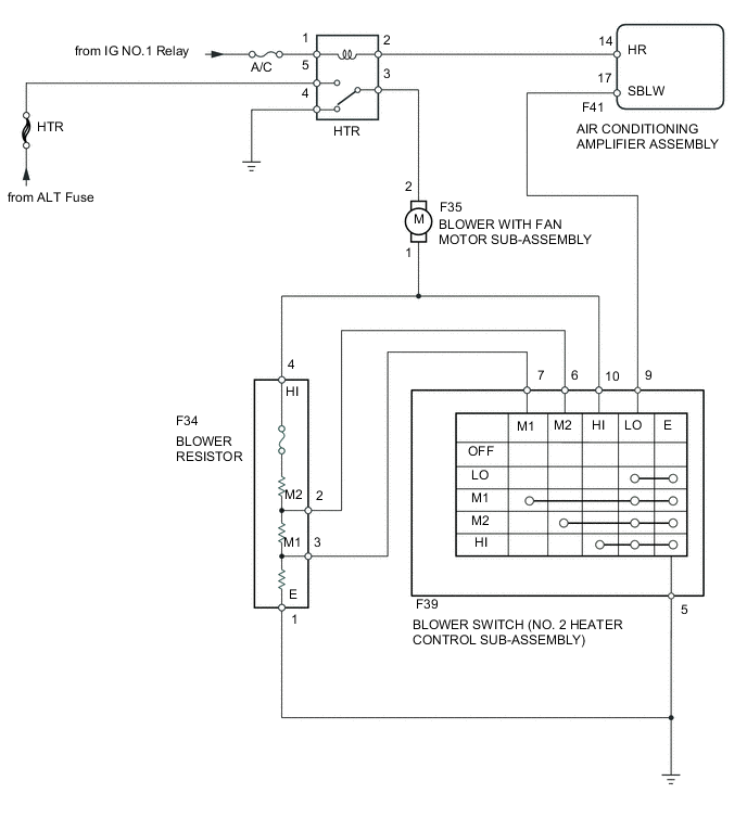
When the blower switch (No. 2 heater control sub-assembly) is set to position 1 or higher, the contact of the HTR relay is closed, current flows to the blower motor, and the blower motor operates. The blower motor speed can be changed by exchanging the ground and the blower resistor circuit with the blower switch (No. 2 heater control sub-assembly).
WIRING DIAGRAM
CAUTION / NOTICE / HINT
Note
Inspect the fuses for circuits related to this system before performing the following inspection procedure.
PROCEDURE
-
INSPECT HTR RELAY
-
Remove the HTR relay.
-
Inspect the HTR relay Click here.
NG 
REPLACE HTR RELAY
OK 
-
-
INSPECT BLOWER WITH FAN MOTOR SUB-ASSEMBLY
-
Remove the blower with fan motor sub-assembly Click here.
-
Inspect the blower with fan motor sub-assembly Click here.
NG
REPLACE BLOWER WITH FAN MOTOR SUB-ASSEMBLY Click here
OK
-
-
CHECK HARNESS AND CONNECTOR (HTR FUSE - HTR RELAY)
-
Remove the HTR relay.
-
Measure the voltage according to the value(s) in the table below.
Standard Voltage Tester Connection Condition Specified Condition 5 - Body ground Always 11 to 14 V 2 - Body ground Ignition switch ON 11 to 14 V
NG
REPAIR OR REPLACE HARNESS OR CONNECTOR
OK
-
-
CHECK HARNESS AND CONNECTOR (HTR RELAY- AIR CONDITIONING AMPLIFIER ASSEMBLY)
-
Disconnect the F41 air conditioning amplifier assembly connector.
-
Measure the resistance according to the value(s) in the table below.
Standard Resistance (Check for Open) Tester Connection Condition Specified Condition 1 - F41-14 (HR) Always Below 1 Ω Standard Resistance (Check for Short) Tester Connection Condition Specified Condition 1 - Body ground Always 10 kΩ or higher
NG
REPAIR OR REPLACE HARNESS OR CONNECTOR
OK
-
-
CHECK HARNESS AND CONNECTOR (HTR RELAY - BLOWER SWITCH (NO. 2 HEATER CONTROL SUB-ASSEMBLY))
-
Disconnect the F39 blower switch (No. 2 heater control sub-assembly) connector.
-
Measure the voltage according to the value(s) in the table below.
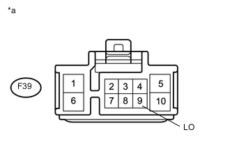
Standard Voltage Tester Connection Condition Specified Condition F39-9 (LO) - Body ground Ignition switch ON 11 to 14 V Text in Illustration *a Front view of wire harness connector
(to No. 2 Heater Control Sub-assembly)
NG
REPAIR OR REPLACE HARNESS OR CONNECTOR
OK
-
-
CHECK HARNESS AND CONNECTOR (HTR RELAY - BLOWER WITH FAN MOTOR SUB-ASSEMBLY)
-
Disconnect the F35 blower with fan motor sub-assembly connector.
-
Measure the voltage according to the value(s) in the table below.
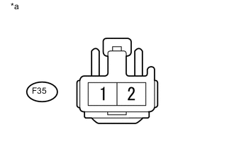
Standard Voltage Tester Connection Condition Specified Condition F35-2 - Body ground Ignition switch ON
Blower switch ON
11 to 14 V Text in Illustration *a Front view of wire harness connector
(to Blower with Fan Motor Sub-assembly)
NG
REPAIR OR REPLACE HARNESS OR CONNECTOR
OK
-
-
CHECK HARNESS AND CONNECTOR (BLOWER WITH FAN MOTOR SUB-ASSEMBLY - BLOWER RESISTOR)
-
Disconnect the F34 blower resistor connector.
-
Measure the resistance according to the value(s) in the table below.
Standard Resistance Tester Connection Condition Specified Condition F34-4 (HI) - F35-1 Always Below 1 Ω
NG
REPAIR OR REPLACE HARNESS OR CONNECTOR
OK
-
-
INSPECT BLOWER RESISTOR
-
Remove the blower resistor Click here.
-
Inspect the blower resistor Click here.
NG
REPLACE BLOWER RESISTOR
OK
-
-
INSPECT BLOWER SWITCH (NO. 2 HEATER CONTROL SUB-ASSEMBLY)
-
Remove the blower switch (No. 2 heater control sub-assembly) Click here.
-
Inspect the blower switch (No. 2 heater control sub-assembly) Click here.
NG
REPLACE NO. 2 HEATER CONTROL SUB-ASSEMBLY
OK
-
-
CHECK HARNESS AND CONNECTOR (BLOWER SWITCH (NO. 2 HEATER CONTROL SUB-ASSEMBLY) - BLOWER RESISTOR)
-
Disconnect the F39 blower switch (No. 2 heater control sub-assembly).
-
Measure the resistance according to the value(s) in the table below.
Standard Resistance Tester Connection Condition Specified Condition F39-5 (E) - F35-1 (E) Always Below 1 Ω F39-10 (HI) - F35-4 (HI) Always Below 1 Ω F39-7 (M1) - F35-3 (M1) Always Below 1 Ω F39-6 (M2) - F35-2 (M2) Always Below 1 Ω
NG
REPAIR OR REPLACE HARNESS OR CONNECTOR
OK
-
-
CHECK HARNESS AND CONNECTOR (BLOWER RESISTOR - BODY GROUND)
-
Disconnect the F34 blower resistor connector.
-
Measure the resistance according to the value(s) in the table below.
Standard Resistance Tester Connection Condition Specified Condition F34-1 (E) - Body ground Always Below 1 Ω
OK
PROCEED TO NEXT SUSPECTED AREA SHOWN IN PROBLEM SYMPTOMS TABLE Click here
NG
REPAIR OR REPLACE HARNESS OR CONNECTOR
-