ELECTRICAL TYPE POWER HEATER SYSTEM TERMINALS OF ECU
-
CHECK AIR CONDITIONING AMPLIFIER (w/ Quick Heater Assembly)

Tech Tips
Check from the rear of the connector while it is connected to the air conditioning amplifier.
Standard Terminal No. (Symbol) Wiring Color Terminal Description Condition Specified Condition F41-8 (TX+) - F41-23 (GND) V - W-B CAN communication line Ignition switch: ON Pulse generation
(see waveform 1)
F41-9 (TX-) - F41-23 (GND) W - W-B CAN communication line Ignition switch: ON Pulse generation
(see waveform 2)
F41-1 (IG+) - F41-23 (GND) V - W-B Power source (IG) Ignition switch: ON 11 to 14 V F41-17 (SBLW) - F41-23 (GND) GR - W-B Blower motor ON signal Ignition switch: ON 11 to 14 V → 0 V Blower switch: 0 → 1 F41-23 (GND) - Body ground W-B - Body ground Ground for main power supply Always Below 1 Ω F41-13 (PTC1) - Body ground SB - Body ground PTC heater relay operation signal Engine idling 11 to 14 V → Below 1 V Set temperature: MAX HOT Engine coolant temperature: Below 75°C (167°F) Ambient temperature: Below 10°C (50°F) Blower switch: OFF → LO F41-19 (PTC2) - Body ground P - Body ground PTC heater relay operation signal Engine idling 11 to 14 V → Below 1 V Set temperature: MAX HOT Engine coolant temperature: Below 70°C (158°F) Ambient temperature: Below 10°C (50°F) Blower switch: OFF → LO F41-20 (PTC3) - Body ground V - Body ground PTC heater relay operation signal Engine idling 11 to 14 V → Below 1 V Set temperature: MAX HOT Engine coolant temperature: Below 65°C (149°F) Ambient temperature: Below 10°C (50°F) Blower switch: OFF → LO If the result is not as specified, there may be a malfunction in the wire harness.
-
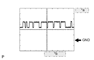
*a 1 V/DIV. *b 10 μsec./DIV. Waveform 1 (Reference) : Using an oscilloscope
CAN Communication Signal Terminal Name F41-8 (TX+) - F41-23 (GND) Tester Range 1 V / DIV., 10 μsec. / DIV. Condition Ignition switch ON Tech Tips
The waveform varies depending on the CAN communication signal.
-
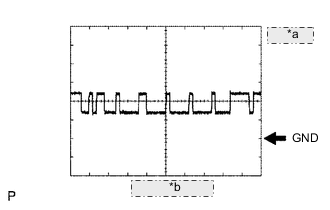
*a 1 V/DIV. *b 10 μsec./DIV. Waveform 2 (Reference) : Using an oscilloscope
CAN Communication Signal Terminal Name F41-9 (TX-) - F41-23 (GND) Tester Range 1 V / DIV., 10 μsec. / DIV. Condition Ignition switch ON Tech Tips
The waveform varies depending on the CAN communication signal.
-
-
CHECK COMBINATION METER ASSEMBLY
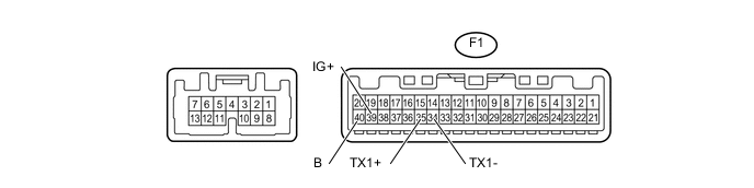
Standard Terminal No. (Symbol) Wiring Color Terminal Description Condition Specified Condition F1-39 (IG+) - Body ground P - Body ground Power source (IG) Ignition switch ON 11 to 14 V F1-40 (B) - Body ground L - Body ground Power source (Back-up) Always 11 to 14 V F1-34 (TX1-) - F1-35 (TX1+)* B - W Ambient temperature sensor signal Ignition switch ON at 25°C (77°F) 1.35 to 1.75 V *: w/ Quick Heater Assembly
If the result is not as specified, there may be a malfunction in the wire harness.