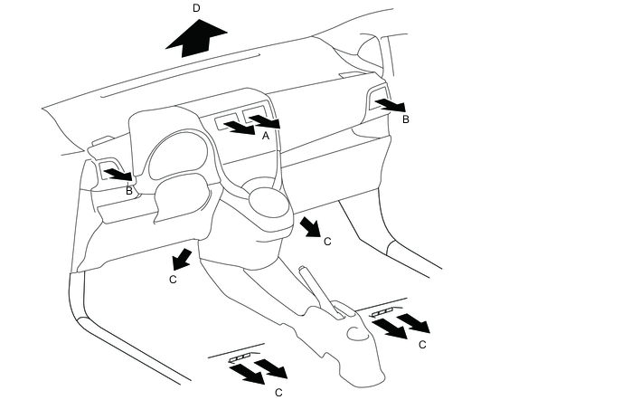
ELECTRICAL TYPE POWER HEATER SYSTEM SYSTEM DESCRIPTION
-
MODE POSITION AND DAMPER OPERATION
-
Front air conditioning mode position and damper operation
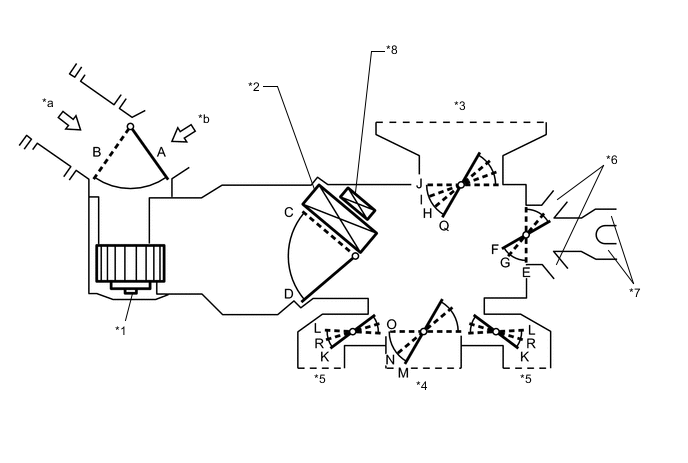
Tech Tips
This Illustration is damper operation image. The number and location of the dampers is different to the actual unit.
Text in Illustration *1 Blower with Fan Motor Sub-assembly *2 Heater Radiator Unit Sub-assembly *3 Front Defroster *4 Center Register *5 Side Register *6 Front Footwell Register Duct *7 Rear Footwell Register Duct *8 Quick Heater Assembly *a Fresh Air *b Recirculated Air Functions of Main Dampers: Control Damper Operation Position Damper Position Operation Air Inlet Control Damper FRESH A Allows outside air to enter. RECIRC B Recirculates internal air. Air Mix Control Damper MIN HOT to MAX HOT Temperature Setting C, D Continuously changes ratio of warm air. Mode Control Damper DEF

O, R, E, Q Blows air from front defroster and side registers. FOOT / DEF

O, K, G, H Blows air from front defroster, side registers, front footwell register, and rear footwell register. FOOT

O, K, F, I Blows air from side registers, front footwell register, and rear footwell register. Also, blows some air from front defroster. BI-LEVEL

N, R, F, J Blows air from center register, side registers, front footwell register and rear footwell register. FACE

M, L, E, J Blows air from center register and side registers.
-
-
AIR OUTLETS AND AIRFLOW VOLUME
-
Air Outlets and Airflow Volume
INDICATION
(MODE)
CTR SIDE FOOTWELL DEFROSTER A B C D FACE


BI-LEVEL


FOOT

FOOT/DEF
DEF
The size of the circle ○ indicates the proportion of airflow volume.
-
-
QUICK HEATER ASSEMBLY
-
General
Quick Heater Control
-
The quick heater assembly is located above the heater radiator unit sub-assembly in the air conditioning radiator assembly.
-
The quick heater assembly consists of a PTC element, aluminum fin, and brass plate. When current is applied to the PTC element, it generates heat to warm the air that passes through the unit.
-
-
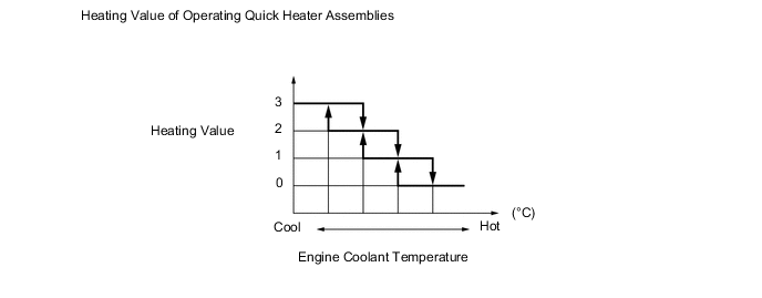
PTC Heater Operating Conditions
-
The on/off function of the quick heater assembly is controlled by the air conditioning amplifier assembly in accordance with the engine coolant temperature, engine speed, air mix setting, and electrical load (alternator power ratio).
-
For example, the heating valve of the operating quick heater assemblies varies depending on the engine coolant temperature, shown as in the graph below:
-
-