AIR CONDITIONING SYSTEM(for Manual Air Conditioning System) PTC Heater Circuit
DESCRIPTION
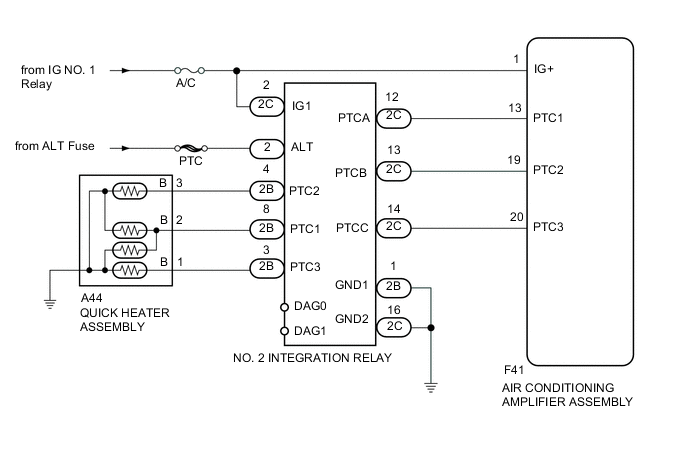
PTC heater relays are closed in accordance with signals from the air conditioning amplifier assembly and power is supplied to the quick heater assembly installed on the radiator heater unit.
WIRING DIAGRAM
PROCEDURE
-
PERFORM ACTIVE TEST USING INTELLIGENT TESTER (HEATER ACTIVE LEVEL)
-
Connect the intelligent tester to the DLC3.
-
Turn the ignition switch to ON.
-
Turn the intelligent tester on.
-
Enter the following menus: Body / Air Conditioner / Active Test.
-
According to the display on the intelligent tester, perform the Active Test.
Air Conditioner Tester Display Test Part Control Range Diagnostic Note Heater Active Level Heater level Min.: 0, Max.: 3 - -
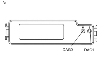
Text in Illustration *a Upper view of No. 2 integration relay Measure the voltage according to the value(s) in the table below while performing the Active Test.
Standard Voltage Tester Connection Condition Specified Condition 0 (DAG0) - Body ground Always 3.5 to 5 V 1 (DAG1) - Body ground Always 3.5 to 5 V
NG 
REPLACE NO. 2 INTEGRATION RELAY
OK 
-
-
CHECK HARNESS AND CONNECTOR (NO. 2 INTEGRATION RELAY - BATTERY)
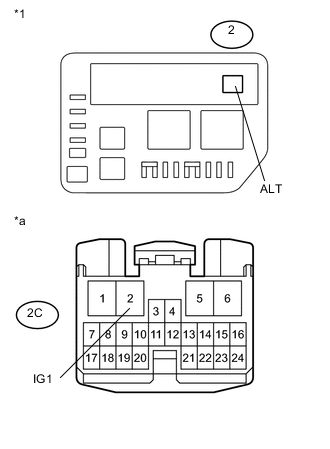
Text in Illustration *1 No. 2 Engine Room Relay Block *a Front view of wire harness connector
(to No. 2 Integration Relay)
-
Remove the No. 2 integration relay from the No. 2 engine room relay block.
-
Measure the voltage according to the value(s) in the table below.
Standard Voltage Tester Connection Condition Specified Condition 2C-2 (IG1) - Body ground Ignition switch ON 11 to 14 V 2 (ALT) - Body ground Always 11 to 14 V
NG
REPAIR OR REPLACE HARNESS OR CONNECTOR
OK
-
-
CHECK HARNESS AND CONNECTOR (NO. 2 INTEGRATION RELAY - BODY GROUND)
-
Measure the resistance according to the value(s) in the table below.
Standard Resistance Tester Connection Condition Specified Condition 2B-1 (GND1) - Body ground Always Below 1 Ω 2C-16 (GND2) - Body ground Always Below 1 Ω
NG
REPAIR OR REPLACE HARNESS OR CONNECTOR
OK
-
-
INSPECT QUICK HEATER ASSEMBLY
-
Disconnect the A44 quick heater assembly connectors.
-
Inspect the quick heater assembly Click here.
NG
REPLACE QUICK HEATER ASSEMBLY Click here
OK
-
-
PERFORM ACTIVE TEST USING INTELLIGENT TESTER (HEATER ACTIVE LEVEL)
-
Connect the intelligent tester to the DLC3.
-
Turn the ignition switch to ON.
-
Turn the intelligent tester on.
-
Enter the following menus: Body / Air Conditioner / Active Test.
-
According to the display on the intelligent tester, perform the Active Test.
Air Conditioner Tester Display Test Part Control Range Diagnostic Note Heater Active Level Heater level Min.: 0, Max.: 3 - -
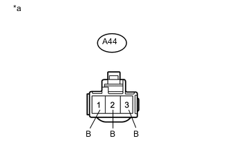
Text in Illustration *a Front view of wire harness connector
(to Quick Heater Assembly)
Measure the voltage according to the value(s) in the table below while performing the Active Test.
Standard Voltage Tester Connection Condition Specified Condition A44-1 (B) - Body ground heater active level 0 Below 1 V heater active level 1 Below 1 V heater active level 2 Below 1 V heater active level 3 11 to 14 V A44-2 (B) - Body ground heater active level 0 Below 1 V heater active level 1 11 to 14 V heater active level 2 11 to 14 V heater active level 3 11 to 14 V A44-3 (B) - Body ground heater active level 0 Below 1 V heater active level 1 Below 1 V heater active level 2 11 to 14 V heater active level 3 11 to 14 V
NG
REPAIR OR REPLACE HARNESS OR CONNECTOR
OK
-
-
CHECK HARNESS AND CONNECTOR (NO. 2 INTEGRATION RELAY - AIR CONDITIONING AMPLIFIER ASSEMBLY)
-
Disconnect the F41 air conditioning amplifier assembly connectors.
-
Measure the resistance according to the value(s) in the table below.
Standard Resistance (Check for Open) Tester Connection Condition Specified Condition 2C-12 (PTCA) - F41-13 (PTC1) Always Below 1 Ω 2C-13 (PTCB) - F41-19 (PTC2) Always Below 1 Ω 2C-14 (PTCC) - F41-20 (PTC3) Always Below 1 Ω Standard Resistance (Check for Short) Tester Connection Condition Specified Condition F41-13 (PTC1) - Body ground Always 10 kΩ or higher F41-19 (PTC2) - Body ground Always 10 kΩ or higher F41-20 (PTC3) - Body ground Always 10 kΩ or higher
OK
REPLACE AIR CONDITIONING AMPLIFIER ASSEMBLY Click here
NG
REPAIR OR REPLACE HARNESS OR CONNECTOR
-