AIR CONDITIONING SYSTEM(for Manual Air Conditioning System) Heater Control Switch Circuit
DESCRIPTION
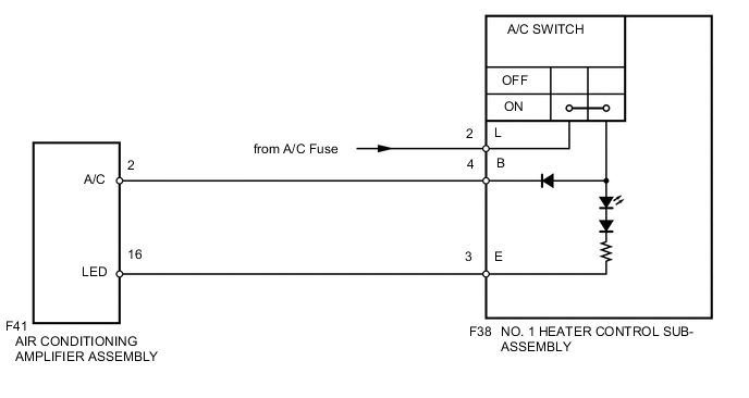
The No. 1 heater control sub-assembly is powered through the A/C fuse. The No. 1 heater control sub-assembly transmits operational signals of each switch to the air conditioning amplifier.
WIRING DIAGRAM
CAUTION / NOTICE / HINT
Note
Inspect the fuses for circuits related to this system before performing the following inspection procedure.
PROCEDURE
-
INSPECT NO. 1 HEATER CONTROL
-
Remove the No. 1 heater control sub-assembly Click here.
-
Inspect the No. 1 heater control sub-assembly Click here.
NG 
REPLACE NO. 1 HEATER CONTROL SUB-ASSEMBLY Click here
OK 
-
-
CHECK HARNESS AND CONNECTOR (NO. 1 HEATER CONTROL SUB-ASSEMBLY - BATTERY)
-
Disconnect the F38 No. 1 heater control sub-assembly connector.
-
Measure the voltage according to the value(s) in the table below.
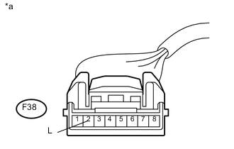
Standard Voltage Tester Connection Switch Condition Specified Condition F38-2 (L) - Body ground Ignition switch off Below 1 V F38-2 (L) - Body ground Ignition switch ON 11 to 14 V Text in Illustration *a Front view of wire harness connector
(to No. 1 Heater Control)
NG
REPAIR OR REPLACE HARNESS OR CONNECTOR
OK
-
-
CHECK HARNESS AND CONNECTOR (NO. 1 HEATER CONTROL SUB-ASSEMBLY - AIR CONDITIONING AMPLIFIER ASSEMBLY)
-
Disconnect the F41 air conditioning amplifier assembly connector.
-
Measure the resistance according to the value(s) in the table below.
Standard Resistance (Check for Open) Tester Connection Condition Specified Condition F38-3 (E) - F41-16 (LED) Always Below 1 Ω F38-4 (B) - F41-2 (A/C) Always Below 1 Ω Standard Resistance (Check for Short) Tester Connection Condition Specified Condition F38-3 (E) - Body ground Always 10 kΩ or higher F38-4 (B) - Body ground Always 10 kΩ or higher
OK
PROCEED TO NEXT SUSPECTED AREA SHOWN IN PROBLEM SYMPTOMS TABLE Click here
NG
REPAIR OR REPLACE HARNESS OR CONNECTOR
-