AIR CONDITIONING SYSTEM(for Automatic Air Conditioning System) DIAGNOSIS SYSTEM
-
DESCRIPTION
-
Air conditioning system data and Diagnostic Trouble Codes (DTCs) can be read through the Data Link Connector 3 (DLC3) of the vehicle. When the system seems to be malfunctioning, use the GTS to check for malfunctions and perform troubleshooting.
-
-
CHECK DLC3
-
Check the DLC3 Click here.
-
-
LIST OF OPERATION METHODS
-
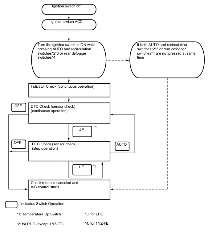
By operating each of the air conditioning control switches as shown in the diagram below, it is possible to enter diagnostic check mode.
-
-
INDICATOR CHECK
-
Turn the ignition switch off.
-
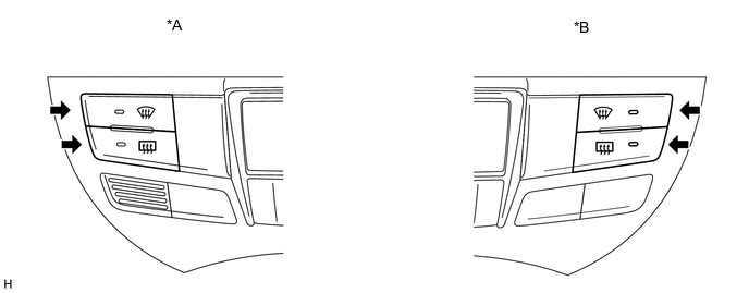
Turn the ignition switch to ON while simultaneously pressing the AUTO switch and the recirculation switch*1*2 or rear defogger switch*3.
*1: for RHD (except 1NZ-FE)
*2: for LHD
*3: for 1NZ-FE
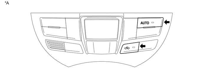
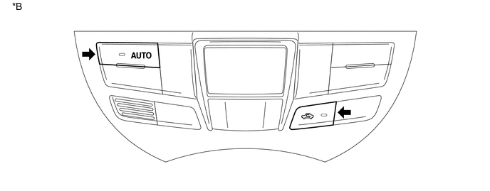
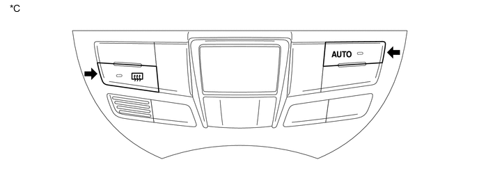
Text in Illustration *A for RHD (except 1NZ-FE) *B for LHD *C for 1NZ-FE - - -
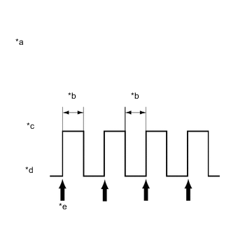
Text in Illustration *a Blinking Pattern *b 1 second *c ON *d OFF *e 4 times Check that all indicators and the display area are turned on and off 4 times in succession at 1-second intervals.
Tech Tips
After the indicator check is completed, the system automatically enters sensor check mode.
-
Press the OFF switch to terminate the panel diagnosis.
-
-
DTC CHECK (SENSOR CHECK)
-
Perform the indicator check.
Tech Tips
After the indicator check is completed, the system automatically enters sensor check mode.
-

Check the sensor check results displayed on the set temperature display.
Results Code Display Present malfunction Blinks Tech Tips
-
The illustration shows the display when code 12 is output.
-
When two or more sensor check codes are detected, the codes are displayed in ascending numerical order.
-
In cases with two or more codes, making them difficult to read, press the temperature up switch to activate the step operation and display them one by one.
-
The codes are displayed in ascending numerical order as the temperature up switch is pressed.
-
-
When any sensor check codes are displayed, refer to the DTC chart Click here.
-
Press the OFF switch to terminate the panel diagnosis.
-
-
PANEL DIAGNOSIS (CLEAR SENSOR CHECK CODE)
-
Inspect, and repair or replace the malfunctioning parts.
-
Clear the sensor check codes.
Text in Illustration *A for RHD *B for LHD
-
While pressing the front defogger switch during sensor check mode, press the rear defogger switch.
-
-
Perform the sensor check and confirm that normal code 00 is displayed.
-