COMBUSTION TYPE POWER HEATER SYSTEM, Diagnostic DTC:054, 056
| DTC Code | DTC Name |
|---|---|
| 054 | High Setting of Flame Cutout |
| 056 | Low Setting of Flame Cutout |
DESCRIPTION
| DTC No. | DTC Detection Condition | Trouble Area |
|---|---|---|
| 054 | Combustion ends abnormally (High output operation). |
|
| 056 | Combustion ends abnormally (Low output operation). |
CAUTION / NOTICE / HINT
CAUTION:
-
In some cases, the combustion heater, air duct and exhaust pipe are extremely hot. When performing the inspection, wear protective gloves and do not touch these parts with bare hands.
-
When performing the inspection, wear a face mask to prevent direct inhalation of exhaust gas.
Tech Tips
Before performing the following inspections, attempt to restart the combustion heater. If the combustion heater is successfully started, confirm that neither DTC 054 nor DTC 056 is output. If neither DTC 054 nor 056 is output, stop troubleshooting because it can be concluded that the system has returned to normal operation.
PROCEDURE
-
INSPECT FUEL PIPE
-
Check that there is no fuel leakage between heater fuel pump sub-assembly and combustion heater assembly.
Result Result Proceed to There is no problem in the fuel pipe. A There is a problem in the fuel pipe. B
B 
REPAIR OR REPLACE FUEL PIPE Click here
A 
-
-
INSPECT AIR DUCT
-
Perform the following checks for the air duct.
-
The air duct is not clogged with foreign matter.
-
Air intake is normal.
-
The air duct is correctly installed to the combustion heater assembly.
-
There are no defects that would cause air to leak from the intake air duct.
Result Result Proceed to There is no problem with the air duct. A There is a problem with the air duct. B -
B
CLEAN OR REPLACE AIR DUCT Click here
A
-
-
INSPECT EXHAUST PIPE
-
Perform the following checks for the exhaust air duct.
-
The exhaust pipe is not clogged with foreign matter.
-
Air exhaust is normal.
-
The exhaust pipe is correctly installed to the combustion heater assembly.
-
There are no defects that would cause air to leak from the exhaust pipe.
Result Result Proceed to There is no problem with the exhaust pipe A There is a problem with the exhaust pipe B -
B
CLEAN OR REPLACE EXHAUST PIPE Click here
A
-
-
INSPECT HEATER FUEL PUMP SUB-ASSEMBLY
-
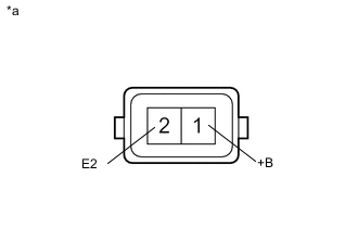
Text in Illustration *a Component without harness connected
(Heater pump assembly)
Measure the resistance according to the value(s) in the table below.
Standard Resistance Tester Connection Condition Specified Condition A30-1 (+B) - A30-2 (E2) Always 9 to 12 Ω -
Inspect heater fuel pump sub-assembly operation.
-
Connect the positive (+) lead from the battery to terminal 1 and the negative (-) lead to terminal 2, and check the pressure of the hose by hand.
CAUTION:
-
This inspection must be done quickly (within 10 seconds) to prevent damage to the heater fuel pump sub-assembly.
-
Always switch the voltage on and off on the battery side, not the heater fuel pump sub-assembly side.
-
Keep the heater fuel pump sub-assembly as far away from the battery as possible.
OK Pressure is applied to the hose. -
-
NG
REPLACE HEATER FUEL PUMP SUB-ASSEMBLY Click here
OK
-
-
REPLACE FUEL PUMP FILTER (HEATER FUEL PUMP SUB-ASSEMBLY)
-
Replace the fuel pump filter (heater fuel pump sub-assembly) with a new one Click here.
-
Check that the condition returns to normal.
OK The combustion heater assembly is ignited normally and it starts operating.
OK
END (FUEL PUMP FILTER IS FAULTY)
NG
REPLACE COMBUSTION HEATER ASSEMBLY Click here
-