SEAT BELT WARNING SYSTEM TERMINALS OF ECU
-
CHECK COMBINATION METER ASSEMBLY
-
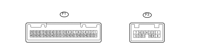
Disconnect the F1 combination meter assembly connector.
-
Measure the resistance and voltage according to the value(s) in the table below.
Terminal No. (Symbol) Wiring Color Terminal Description Condition Specified Condition F1-40 (B) - Body ground L - Body ground Combination meter +B line Always 11 to 14 V F1-39 (IG+) - Body ground P - Body ground Combination meter IG line Ignition switch ON 11 to 14 V F1-21 (ET) - Body ground W-B - Body ground Ground Always Below 1 Ω If the result is not as specified, there may be a malfunction on the wire harness side.
-
Reconnect the F1 combination meter assembly connector.
-
Measure the voltage according to the value(s) in the table below.
Terminal No. (Symbol) Wiring Color Terminal Description Condition Specified Condition F1-7 (P/SB) - Body ground P - Body ground Front passenger seat belt signal Front passenger seat occupied, seat belt fastened Below 1 V Front passenger seat occupied, seat belt unfastened 11 to 14 V F1-24 (RLSB) - Body ground V - Body ground Rear seat belt LH signal Rear seat belt LH fastened Below 1 V Rear seat belt LH unfastened 11 to 14 V F1-25 (RCSB) - Body ground R - Body ground Rear seat center belt signal Rear seat center belt fastened Below 1 V Rear seat center belt unfastened 11 to 14 V F1-26 (RRSB) - Body ground BE - Body ground Rear seat belt RH signal Rear seat belt RH fastened Below 1 V Rear seat belt RH unfastened 11 to 14 V F1-1 (RLMT) - Body ground GR - Body ground Rear seat belt LH warning signal Rear seat belt LH fastened Below 1 V Rear seat belt LH unfastened 11 to 14 V F1-2 (RCMT) - Body ground G - Body ground Rear seat center belt warning signal Rear seat center belt fastened Below 1 V Rear seat center belt unfastened 11 to 14 V F1-3 (RRMT) - Body ground B - Body ground Rear seat belt RH warning signal Rear seat belt RH fastened Below 1 V Rear seat belt RH unfastened 11 to 14 V If the result is not as specified, the meter may have a malfunction.
-
-
CHECK MAIN BODY ECU (INSTRUMENT PANEL JUNCTION BLOCK ASSEMBLY)
-
w/o Theft Deterrent System
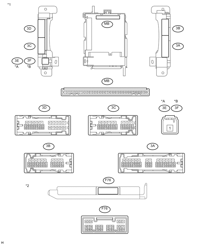
Text in Illustration *A for LHD *B for RHD *1 Instrument Panel Junction Block Assembly *2 Main Body ECU
(Multiplex Network Body ECU)
-
w/ Theft Deterrent System
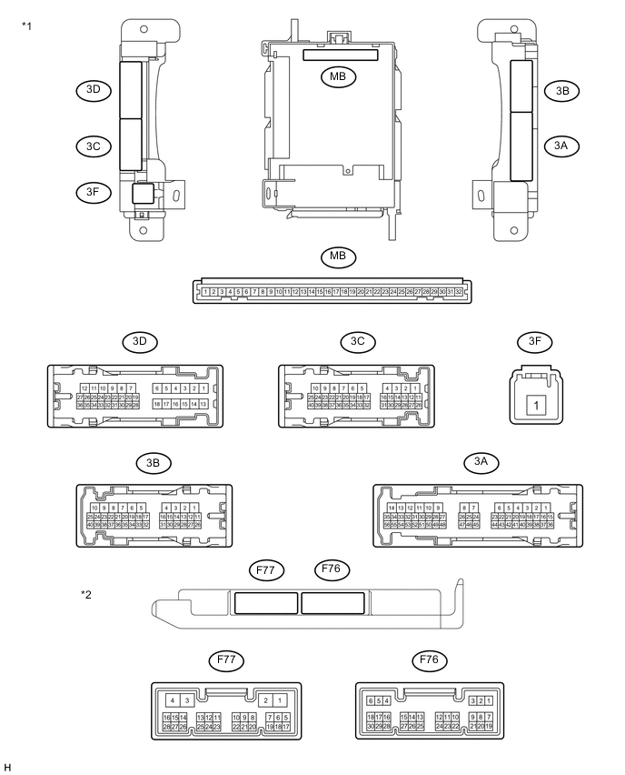
Text in Illustration *1 Instrument Panel Junction Block Assembly *2 Main Body ECU
(Multiplex Network Body ECU)
-
Remove the main body ECU (multiplex network body ECU) from the instrument panel junction block assembly Click here.
-
Measure the resistance and voltage according to the value(s) in the table below.
Terminal No. (Symbol) Wiring Color Terminal Description Condition Specified Condition MB-11 (GND1) - Body ground - Ground Always Below 1 Ω MB-31 (ALTB) - Body ground* - Battery (ECU power source) Always 11 to 14 V MB-30 (BECU) - Body ground - Battery (ECU power source) Always 11 to 14 V MB-32 (IG) - Body ground - Ignition power supply Ignition switch ON 11 to 14 V MB-29 (ACC) - Body ground - Ignition power supply Ignition switch ACC 11 to 14 V F76-6 (LRCY) - Body ground G - Body ground Rear door courtesy light switch signal Rear door open Below 1 Ω Rear door closed 10 kΩ or higher *: w/ Rear Fog Light
If the result is not as specified, there may be a malfunction on the wire harness side.
-
Install the main body ECU (multiplex network body ECU) to the instrument panel junction block assembly Click here.
-
Measure the voltage according to the value(s) in the table below.
Terminal No. (Symbol) Wiring Color Terminal Description Condition Specified Condition 3D-34 (DBKL) - Body ground W - Body ground Driver seat belt warning signal Driver seat belt fastened 11 to 14 V Driver seat belt unfastened Below 1 V F76-13 (CANL) - Body ground W - Body ground CAN communication line Ignition switch ON Pulse generation F76-14 (CANH) - Body ground R - Body ground CAN communication line Ignition switch ON Pulse generation If the result is not as specified, the main body ECU (multiplex network body ECU) may have a malfunction.
-