SPIRAL CABLE INSPECTION
PROCEDURE
-
INSPECT SPIRAL CABLE SUB-ASSEMBLY (w/o Steering Pad Switch)
Note
-
Do not remove the steering sensor from the spiral cable sub-assembly.
-
If there is a malfunction in the steering sensor, replace the spiral cable sub-assembly.
-
If there are any defects as mentioned below, replace the spiral cable sub-assembly with a new one:
-
Scratches, cracks, dents or chips on the connector or the spiral cable sub-assembly.
-
-
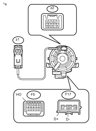
Text in Illustration *a Component without harness connected
(Spiral Cable Sub-assembly)
Inspect the spiral cable sub-assembly.
-
Measure the resistance according to the value(s) in the table below.
Note
To avoid breaking the spiral cable sub-assembly, do not turn the spiral cable sub-assembly more than necessary.
Standard Resistance Tester Connection Condition Specified Condition F5-8 - z2-1
(HO)
Always 3 Ω or less F17-1 - z1-2
(D+)
Always Below 1Ω F17-2 - z1-1
(D-)
Always Below 1Ω If the value is not within the specified range, replace the spiral cable sub-assembly.
-
-
-
INSPECT SPIRAL CABLE SUB-ASSEMBLY (w/ Steering Pad Switch)
Note
-
Do not remove the steering sensor from the spiral cable sub-assembly.
-
If there is a malfunction in the steering sensor, replace the spiral cable sub-assembly with steering sensor.
-
If there are any defects as mentioned below, replace the spiral cable sub-assembly with a new one:
-
Scratches, cracks, dents or chips on the connector or the spiral cable sub-assembly.
-
-
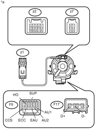
Text in Illustration *a Component without harness connected
(Spiral Cable Sub-assembly)
Inspect the spiral cable sub-assembly.
-
Measure the resistance according to the value(s) in the table below.
Note
To avoid breaking the spiral cable sub-assembly, do not turn the spiral cable sub-assembly more than necessary.
Standard Resistance Tester Connection Condition Specified Condition F5-8 - z2-1
(HO)
Always 3 Ω or less F5-9 - z2-2
(SUP)
Always 3 Ω or less F5-10 - z2-3
(SDN)
Always 3 Ω or less F5-4 - z2-8
(EAU)
Always 3 Ω or less F5-5 - z2-9
(AU2)
Always 3 Ω or less F5-6 - z2-10
(AU1)
Always 3 Ω or less F5-1 - z7-3
(CCS)
Always 3 Ω or less F5-2 - z7-4
(ECC)
Always 3 Ω or less F5-2 - z2-6
(ECC)
Always 3 Ω or less F17-1 - z1-2
(D+)
Always Below 1Ω F17-2 - z1-1
(D-)
Always Below 1Ω If the value is not within the specified range, replace the spiral cable sub-assembly.
-
-