AIRBAG SYSTEM TC and CG Terminal Circuit
DESCRIPTION
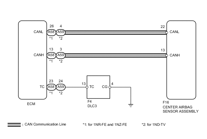
DTC output mode is set by connecting terminals TC and CG of the DLC3.
The DTCs are displayed by blinking the SRS warning light.
Tech Tips
-
Make sure that DTCs which relate to the CAN communication system are not output. If any of these DTCs are output, check the CAN communication system Click here.
-
When a warning light keeps blinking, a short to ground in the wiring of terminal TC of the DLC3 or an internal ground short in an ECU is suspected.
-
The DTC output mode signal is transmitted through the CAN to each ECU including the center airbag sensor assembly. Thus if no systems enter DTC output mode, the ECM may have a malfunction.
WIRING DIAGRAM
PROCEDURE
-
CHECK HARNESS AND CONNECTOR (DLC3 - ECM)
-
Turn the ignition switch off.
-
Disconnect the connector from the ECM.
-
Measure the resistance according to the value(s) in the table below.
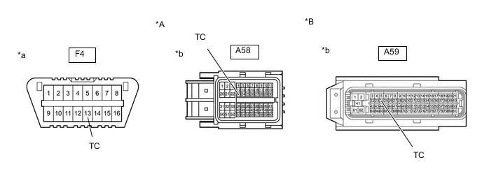
Standard Resistance for 1NR-FE and 1NZ-FE Tester Connection Condition Specified Condition F4-13 (TC) -
A58-23 (TC)
Always Below 1 Ω for 1ND-TV Tester Connection Condition Specified Condition F4-13 (TC) -
A59-24 (TC)
Always Below 1 Ω Text in Illustration *A for 1NR-FE and 1NZ-FE *B for 1ND-TV *a Front view of DLC3 *b Front view of wire harness connector
(to ECM)
NG 
REPAIR OR REPLACE HARNESS OR CONNECTOR
OK 
-
-
CHECK HARNESS AND CONNECTOR (CG OF DLC3 - BODY GROUND)
-
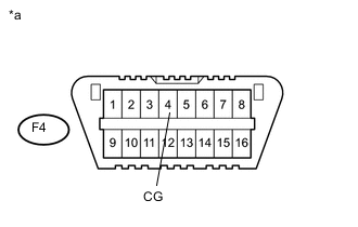
Text in Illustration *a Front view of DLC3 Measure the resistance according to the value(s) in the table below.
Standard Resistance Tester Connection Condition Specified Condition F4-4 (CG) -
Body ground
Always Below 1 Ω
NG
REPAIR OR REPLACE HARNESS OR CONNECTOR
OK
-
-
CHECK HARNESS AND CONNECTOR (TC OF ECM)
-
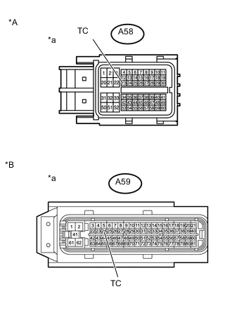
Text in Illustration *A for 1NR-FE and 1NZ-FE *B for 1ND-TV *a Front view of wire harness connector
(to ECM)
Measure the resistance according to the value(s) in the table below.
Standard Resistance for 1NR-FE and 1NZ-FE Tester Connection Condition Specified Condition A58-23 (TC) -
Body ground
Always 1 MΩ or higher for 1ND-TV Tester Connection Condition Specified Condition A59-24 (TC) -
Body ground
Always 1 MΩ or higher
NG
REPAIR OR REPLACE HARNESS OR CONNECTOR
OK
-
-
REPLACE ECM
-
Replace the ECM.
-
Check for DTCs of the ECM.
-
for 1NR-FE Click here
-
for 1NZ-FE Click here
-
for 1ND-TV Click here
Result Result Proceed to Normal system code is output A DTC is output (for 1NR-FE) B DTC is output (for 1NZ-FE) C DTC is output (for 1ND-TV) D DTC output mode is set (except center airbag sensor assembly) E -
A
END
B
GO TO INSPECTION PROCEDURE OF DTC OUTPUT Click here
C
GO TO INSPECTION PROCEDURE OF DTC OUTPUT Click here
D
GO TO INSPECTION PROCEDURE OF DTC OUTPUT Click here
E
REPLACE CENTER AIRBAG SENSOR ASSEMBLY Click here
-