LIGHTING SYSTEM Door Courtesy Switch Circuit
DESCRIPTION
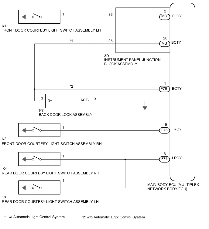
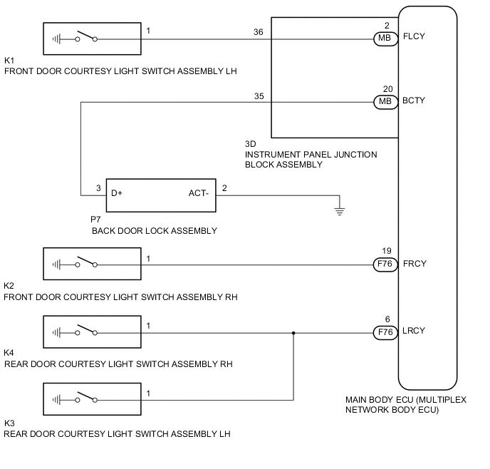
The main body ECU (multiplex network body ECU) receives a door open/closed signal from each door courtesy light switch assembly.
WIRING DIAGRAM
-
w/o Rear Fog Light
-
w/ Rear Fog Light
CAUTION / NOTICE / HINT
Note
Initialization is necessary when the main body ECU (multiplex network body ECU) is replaced* Click here.
-
*: w/ Automatic Light Control System
PROCEDURE
-
READ VALUE USING INTELLIGENT TESTER (DOOR COURTESY)
-
Using the intelligent tester, read the Data List Click here.
Main Body Tester Display Measurement Item/Range Normal Condition Diagnostic Note FR Door Courtesy Front door courtesy light switch (for RH) signal / ON or OFF ON: Front door RH closed
OFF: Front door RH opened
- FL Door Courtesy Front door courtesy light switch (for LH) signal / ON or OFF ON: Front door LH closed
OFF: Front door LH opened
- RL Door Courtesy SW Rear door courtesy light switch (for LH) signal / ON or OFF ON: Rear door opened
OFF: Rear door closed
- RR Door Courtesy SW Rear door courtesy light switch (for RH) signal / ON or OFF ON: Rear door opened
OFF: Rear door closed
- Back Door Courtesy SW Back door courtesy light switch signal / ON or OFF ON: Back door opened
OFF: Back door closed
- Result Result Proceed to NG (Front door courtesy light switch RH does not operate) A NG (Front door courtesy light switch LH does not operate) B NG (Rear door courtesy light switch does not operate) C NG (Back door courtesy light switch does not operate) D OK E
B 
INSPECT FRONT DOOR COURTESY LIGHT SWITCH ASSEMBLY LH Click here
C
INSPECT REAR DOOR COURTESY LIGHT SWITCH ASSEMBLY (LH OR RH) Click here
D
INSPECT BACK DOOR LOCK ASSEMBLY Click here
E 
PROCEED TO NEXT SUSPECTED AREA SHOWN IN PROBLEM SYMPTOMS TABLE Click here
A 
-
-
INSPECT FRONT DOOR COURTESY LIGHT SWITCH ASSEMBLY RH
-
Remove the front door courtesy light switch assembly RH Click here.
-
Inspect the front door courtesy light switch assembly RH Click here.
NG
REPLACE FRONT DOOR COURTESY LIGHT SWITCH ASSEMBLY RH Click here
OK
-
-
CHECK HARNESS AND CONNECTOR (MAIN BODY ECU - FRONT DOOR COURTESY LIGHT SWITCH RH)
-
Disconnect the F76 main body ECU (multiplex network body ECU) connector.
-
Measure the resistance according to the value(s) in the table below.
Standard Resistance (Check for Open) Tester Connection Condition Specified Condition K2-1 - F76-19 (FRCY) Always Below 1 Ω Standard Resistance (Check for Short) Tester Connection Condition Specified Condition K2-1 - Body ground Always 10 kΩ or higher
OK
REPLACE MAIN BODY ECU (MULTIPLEX NETWORK BODY ECU) Click here
NG
REPAIR OR REPLACE HARNESS OR CONNECTOR
-
-
INSPECT FRONT DOOR COURTESY LIGHT SWITCH ASSEMBLY LH
-
Remove the front door courtesy light switch assembly LH Click here.
-
Inspect the front door courtesy light switch assembly LH Click here.
NG
REPLACE FRONT DOOR COURTESY LIGHT SWITCH ASSEMBLY LH Click here
OK
-
-
CHECK HARNESS AND CONNECTOR (FRONT DOOR COURTESY LIGHT SWITCH LH - INSTRUMENT PANEL JUNCTION BLOCK)
-
Disconnect the 3D instrument panel junction block assembly connector.
-
Measure the resistance according to the value(s) in the table below.
Standard Resistance (Check for Open) Tester Connection Condition Specified Condition K1-1 - 3D-36 Always Below 1 Ω Standard Resistance (Check for Short) Tester Connection Condition Specified Condition K1-1 - Body ground Always 10 kΩ or higher
NG
REPAIR OR REPLACE HARNESS OR CONNECTOR
OK
-
-
INSPECT INSTRUMENT PANEL JUNCTION BLOCK ASSEMBLY
-
Remove the instrument panel junction block assembly Click here.
-
Remove the main body ECU (multiplex network body ECU) from the instrument panel junction block assembly.
-
Measure the resistance according to the value(s) in the table below.
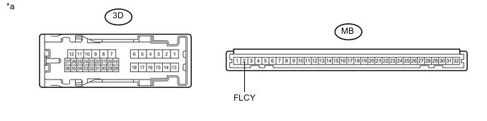
Text in Illustration *a Component without harness connected
(Instrument Panel Junction Block Assembly)
- - Standard Resistance Tester Connection Condition Specified Condition 3D-36 - MB-2 (FLCY) Always Below 1 Ω
OK
REPLACE MAIN BODY ECU (MULTIPLEX NETWORK BODY ECU) Click here
NG
REPLACE INSTRUMENT PANEL JUNCTION BLOCK ASSEMBLY Click here
-
-
INSPECT REAR DOOR COURTESY LIGHT SWITCH ASSEMBLY (LH OR RH)
-
Remove the rear door courtesy light switch assembly Click here.
-
Inspect the rear door courtesy light switch assembly Click here.
NG
REPLACE REAR DOOR COURTESY LIGHT SWITCH ASSEMBLY (LH OR RH) Click here
OK
-
-
CHECK HARNESS AND CONNECTOR (MAIN BODY ECU - REAR DOOR COURTESY LIGHT SWITCH (LH OR RH))
-
Disconnect the F76 main body ECU (multiplex network body ECU) connector.
-
Measure the resistance according to the value(s) in the table below.
Standard Resistance (Check for Open) for LH Tester Connection Condition Specified Condition K3-1 - F76-6 (LRCY) Always Below 1 Ω for RH Tester Connection Condition Specified Condition K4-1 - F76-6 (LRCY) Always Below 1 Ω Standard Resistance (Check for Short) Tester Connection Condition Specified Condition F76-6 (LRCY) - Body ground Always 10 kΩ or higher
OK
REPLACE MAIN BODY ECU (MULTIPLEX NETWORK BODY ECU) Click here
NG
REPAIR OR REPLACE HARNESS OR CONNECTOR
-
-
INSPECT BACK DOOR LOCK ASSEMBLY
-
Remove the back door lock assembly Click here.
-
Inspect the back door lock assembly Click here.
Tech Tips
Inspect the door courtesy switch only.
NG
REPLACE BACK DOOR LOCK ASSEMBLY Click here
OK
-
-
CHECK VEHICLE CONDITION
-
Check the vehicle condition.
Result Result Proceed to w/ Rear Fog Light A w/o Rear Fog Light B
B
CHECK VEHICLE CONDITION Click here
A
-
-
CHECK HARNESS AND CONNECTOR (BACK DOOR LOCK - INSTRUMENT PANEL JUNCTION BLOCK, BODY GROUND)
-
Disconnect the 3D instrument panel junction block assembly connector.
-
Measure the resistance according to the value(s) in the table below.
Standard Resistance (Check for Open) Tester Connection Condition Specified Condition P7-3 (D+) - 3D-35 Always Below 1 Ω P7-2 (ACT-) - Body ground Always Below 1 Ω Standard Resistance (Check for Short) Tester Connection Condition Specified Condition P7-3 (D+) - Body ground Always 10 kΩ or higher
NG
REPAIR OR REPLACE HARNESS OR CONNECTOR
OK
-
-
INSPECT INSTRUMENT PANEL JUNCTION BLOCK ASSEMBLY
-
Remove the instrument panel junction block assembly Click here.
-
Remove the main body ECU (multiplex network body ECU) from the instrument panel junction block assembly.
-
Measure the resistance according to the value(s) in the table below.
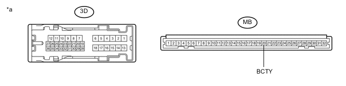
Text in Illustration *a Component without harness connected
(Instrument Panel Junction Block Assembly)
- - Standard Resistance Tester Connection Condition Specified Condition 3D-35 - MB-20 (BCTY) Always Below 1 Ω
OK
REPLACE MAIN BODY ECU (MULTIPLEX NETWORK BODY ECU) Click here
NG
REPLACE INSTRUMENT PANEL JUNCTION BLOCK ASSEMBLY Click here
-
-
CHECK VEHICLE CONDITION
-
Check the vehicle condition.
Result Result Proceed to w/o Automatic Light Control System A w/ Automatic Light Control System B
B
CHECK CHECK HARNESS AND CONNECTOR (BACK DOOR LOCK - INSTRUMENT PANEL JUNCTION BLOCK, BODY GROUND) Click here
A
-
-
CHECK HARNESS AND CONNECTOR (BACK DOOR LOCK - MAIN BODY ECU, BODY GROUND)
-
Disconnect the F76 main body ECU (multiplex network body ECU) connector.
-
Measure the resistance according to the value(s) in the table below.
Standard Resistance (Check for Open) Tester Connection Condition Specified Condition P7-3 (D+) - F76-1 (BCTY) Always Below 1 Ω P7-2 (ACT-) - Body ground Always Below 1 Ω Standard Resistance (Check for Short) Tester Connection Condition Specified Condition P7-3 (D+) - Body ground Always 10 kΩ or higher
OK
REPLACE MAIN BODY ECU (MULTIPLEX NETWORK BODY ECU) Click here
NG
REPAIR OR REPLACE HARNESS OR CONNECTOR
-
-
CHECK CHECK HARNESS AND CONNECTOR (BACK DOOR LOCK - INSTRUMENT PANEL JUNCTION BLOCK, BODY GROUND)
-
Disconnect the 3D instrument panel junction block assembly connector.
-
Measure the resistance according to the value(s) in the table below.
Standard Resistance (Check for Open) Tester Connection Condition Specified Condition P7-3 (D+) - 3D-35 Always Below 1 Ω P7-2 (ACT-) - Body ground Always Below 1 Ω Standard Resistance (Check for Short) Tester Connection Condition Specified Condition P7-3 (D+) - Body ground Always 10 kΩ or higher
NG
REPAIR OR REPLACE HARNESS OR CONNECTOR
OK
-
-
INSPECT INSTRUMENT PANEL JUNCTION BLOCK ASSEMBLY
-
Remove the instrument panel junction block assembly Click here.
-
Remove the main body ECU (multiplex network body ECU) from the instrument panel junction block assembly.
-
Measure the resistance according to the value(s) in the table below.
Text in Illustration *a Component without harness connected
(Instrument Panel Junction Block Assembly)
- - Standard Resistance Tester Connection Condition Specified Condition 3D-35 - MB-20 (BCTY) Always Below 1 Ω
OK
REPLACE MAIN BODY ECU (MULTIPLEX NETWORK BODY ECU) Click here
NG
REPLACE INSTRUMENT PANEL JUNCTION BLOCK ASSEMBLY Click here
-