LIGHTING SYSTEM TERMINALS OF ECU
-
CHECK INSTRUMENT PANEL JUNCTION BLOCK ASSEMBLY AND MAIN BODY ECU (MULTIPLEX NETWORK BODY ECU) (w/o Theft Deterrent System)
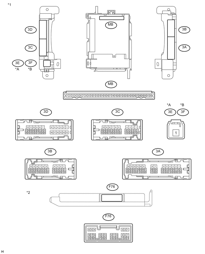
Text in Illustration *A for LHD *B for RHD *1 Instrument Panel Junction Block Assembly *2 Main Body ECU (Multiplex Network Body ECU)
-
Disconnect the 3A, 3B, 3C and 3E*1 or 3F*2 instrument panel junction block assembly connectors.
-
*1: for LHD
-
*2: for RHD
-
-
Measure the voltage and resistance according to the value(s) in the table below.
Standard Voltage Terminal No. (Symbol) Wiring Color Terminal Description Condition Specified Condition 3A-29 - Body ground SB - Body ground IG power supply Ignition switch ON 11 to 14 V 3B-37 - Body ground L - Body ground ACC power supply Ignition switch ACC 11 to 14 V 3C-4 - Body ground G - Body ground Battery power supply Always 11 to 14 V 3C-21 - Body ground L - Body ground Battery power supply Always 11 to 14 V 3E-1*1 - Body ground B - Body ground Battery power supply Always 11 to 14 V 3F-1*2 - Body ground B - Body ground Battery power supply Always 11 to 14 V
-
*1: for LHD
-
*2: for RHD
Standard Resistance Terminal No. (Symbol) Wiring Color Terminal Description Condition Specified Condition 3B-8 - Body ground W-B - Body ground Ground Always Below 1 Ω If the result is not as specified, there may be a malfunction in the wire harness.
-
-
Reconnect the 3A, 3B, 3C and 3E*1 or 3F*2 instrument panel junction block assembly connectors.
-
*1: for LHD
-
*2: for RHD
-
-
Measure the voltage according to the value(s) in the table below.
Standard Voltage Terminal No. (Symbol) Wiring Color Terminal Description Condition Specified Condition F76-1 (BCTY)*1 - Body ground B - Body ground Back door courtesy switch signal Back door opened Below 1 V Back door closed 11 to 14 V F76-6 (LRCY) - Body ground G - Body ground Rear door courtesy light switch signal Rear door opened Below 1 V Rear door closed Pulse generation*2 11 to 14 V*7 F76-7 (LSFL)*2,*3 - Body ground L - Body ground Front door LH unlock detection switch signal Front door LH locked 11 to 14 V Front door LH unlocked Below 1 V F76-13 (CANL) - Body ground W - Body ground CAN communication Ignition switch ON Pulse generation F76-14 (CANH) - Body ground R - Body ground CAN communication Ignition switch ON Pulse generation F76-18 (LSFR) - Body ground LG - Body ground Front door RH unlock detection switch signal Front door RH locked Pulse generation Front door RH unlocked Below 1 V F76-19 (FRCY) - Body ground Y - Body ground Front door courtesy light switch RH signal Front door RH opened Below 1 V Front door RH closed Pulse generation*2 11 to 14 V*7 3A-5 - Body ground SB - Body ground Battery power supply Always 11 to 14 V 3A-28*2 - Body ground R - Body ground Parking brake switch signal Parking brake applied Below 1 V Parking brake released 11 to 14 V 3A-40 - Body ground L - Body ground IG power supply Ignition switch ON 11 to 14 V 3A-54*4 - Body ground Y - Body ground IG power supply Ignition switch ON 11 to 14 V 3B-6 - Body ground B - Body ground Illuminated entry drive signal Lights off 11 to 14 V Lights on Below 1 V 3B-33*5 - Body ground LG - Body ground Footwell light LH drive signal Lights on Below 1 V Dim illumination Pulse generation 3B-34*5 - Body ground V - Body ground Footwell light RH drive signal Lights on Below 1 V Dim illumination Pulse generation 3D-6 - Body ground L - Body ground Luggage room light power supply Always 11 to 14 V 3D-24*2,*3 - Body ground Y - Body ground Rear door unlock detection switch signal Rear door locked 11 to 14 V Rear door unlocked Below 1 V 3D-25*2,*3 - Body ground V - Body ground Rear door unlock detection switch signal Rear door locked 11 to 14 V Rear door unlocked Below 1 V 3D-35*2,*6 - Body ground B - Body ground Back door courtesy switch signal Back door opened Below 1 V Back door closed Pulse generation*2 11 to 14 V*6 3D-36 - Body ground L - Body ground Front door courtesy light switch LH signal Front door LH opened Below 1 V Front door LH closed Pulse generation*2 11 to 14 V*7
-
*1: w/o Rear Fog Light and w/o Automatic Light Control System
-
*2: w/ Rear Fog Light
-
*3: w/o Rear Fog Light and w/ Entry and Start System
-
*4: w/o Stop and Start System
-
*5: w/ Footwell Light
-
*6: w/o Rear Fog Light and w/ Automatic Light Control System
-
*7: w/o Rear Fog Light
Tech Tips
If the result is not as specified, the main body ECU (multiplex network body ECU) or instrument panel junction block assembly may have a malfunction.
-
-
-
CHECK INSTRUMENT PANEL JUNCTION BLOCK ASSEMBLY AND MAIN BODY ECU (MULTIPLEX NETWORK BODY ECU) (w/ Theft Deterrent System)
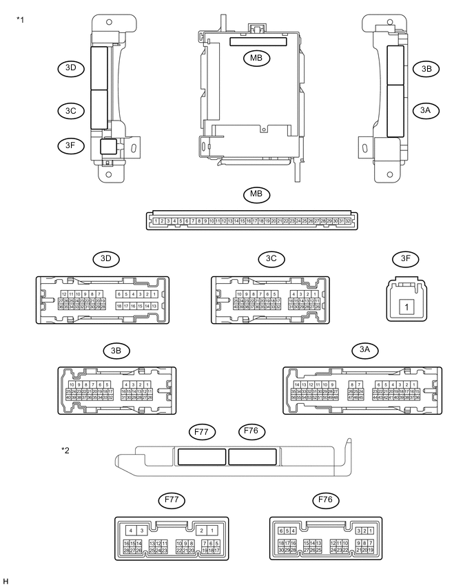
Text in Illustration *1 Instrument Panel Junction Block Assembly *2 Main Body ECU (Multiplex Network Body ECU)
-
Disconnect the 3A, 3B, 3C and 3F instrument panel junction block assembly connectors.
-
Measure the resistance according to the value(s) in the table below.
Standard Voltage Terminal No. (Symbol) Wiring Color Terminal Description Condition Specified Condition 3A-29 - Body ground SB - Body ground IG power supply Ignition switch ON 11 to 14 V 3B-37 - Body ground L - Body ground ACC power supply Ignition switch ACC 11 to 14 V 3C-4 - Body ground G - Body ground Battery power supply Always 11 to 14 V 3C-21 - Body ground L - Body ground Battery power supply Always 11 to 14 V 3F-1 - Body ground B - Body ground Battery power supply Always 11 to 14 V Standard Resistance Terminal No. (Symbol) Wiring Color Terminal Description Condition Specified Condition 3B-8 - Body ground W-B - Body ground Ground Always Below 1 Ω If the result is not as specified, there may be a malfunction in the wire harness.
-
Reconnect the 3A, 3B, 3C and 3F instrument panel junction block assembly connectors.
-
Measure the voltage according to the value(s) in the table below.
Standard Voltage Terminal No. (Symbol) Wiring Color Terminal Description Condition Specified Condition F76-6 (LRCY) - Body ground G - Body ground Rear door courtesy light switch signal Rear door opened Below 1 V Rear door closed Pulse generation F76-7 (LSFL) - Body ground L - Body ground Front door LH unlock detection switch signal Front door LH locked 11 to 14 V Front door LH unlocked Below 1 V F76-13 (CANL) - Body ground W - Body ground CAN communication Ignition switch ON Pulse generation F76-14 (CANH) - Body ground R - Body ground CAN communication Ignition switch ON Pulse generation F76-18 (LSFR) - Body ground LG - Body ground Front door RH unlock detection switch signal Front door RH locked Pulse generation Front door RH unlocked Below 1 V F76-19 (FRCY) - Body ground Y - Body ground Front door courtesy light switch RH signal Front door RH opened Below 1 V Front door RH closed Pulse generation 3A-5 - Body ground SB - Body ground Battery power supply Always 11 to 14 V 3A-28 - Body ground R - Body ground Parking brake switch signal Parking brake applied Below 1 V Parking brake released 11 to 14 V 3A-40 - Body ground L - Body ground IG power supply Ignition switch ON 11 to 14 V 3A-54 - Body ground Y - Body ground IG power supply Ignition switch ON 11 to 14 V 3B-6 - Body ground B - Body ground Luggage room light power supply Always 11 to 14 V 3B-33 - Body ground LG - Body ground Footwell light LH signal Lights on Below 1 V Dim illumination Pulse generation 3B-34 - Body ground V - Body ground Footwell light RH signal Lights on Below 1 V Dim illumination Pulse generation 3D-6 - Body ground L - Body ground Luggage room light signal Lights off 11 to 14 V Lights on Below 1 V 3D-24 - Body ground Y - Body ground Rear door unlock detection switch signal Rear door locked 11 to 14 V Rear door unlocked Below 1 V 3D-25 - Body ground V - Body ground Rear door unlock detection switch signal Rear door locked 11 to 14 V Rear door unlocked Below 1 V 3D-35 - Body ground B - Body ground Back door courtesy switch signal Back door opened Below 1 V Back door closed Pulse generation 3D-36 - Body ground L - Body ground Front door courtesy light switch LH signal Front door LH opened Below 1 V Front door LH closed Pulse generation Tech Tips
If the result is not as specified, the main body ECU (multiplex network body ECU) or instrument panel junction block assembly may have a malfunction.
-
-
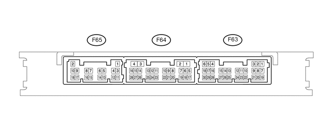
CHECK CERTIFICATION ECU (SMART KEY ECU ASSEMBLY)
-
Measure the resistance according to the value(s) in the table below.
Standard Resistance Terminal No. (Symbol) Wiring Color Terminal Description Condition Specified Condition F63-16 (SWIL) - Body ground G - Body ground Engine switch illumination drive signal Engine switch illumination on 9 to 14 V Engine switch illumination off Below 2 V F63-24 (AGND) - Body ground G - Body ground Ground Always Below 1 Ω If the result is not as specified, there may be a malfunction on the wire harness side.
-