THEFT DETERRENT SYSTEM ECU Power Source Circuit
DESCRIPTION
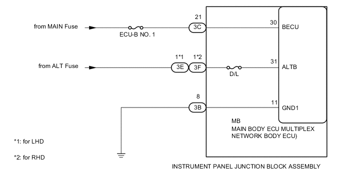
This circuit provides power for main body ECU (multiplex network body ECU) operation.
WIRING DIAGRAM
CAUTION / NOTICE / HINT
Note
Inspect the fuses for circuits related to this system before performing the following inspection procedure.
PROCEDURE
-
CHECK HARNESS AND CONNECTOR (BATTERY - INSTRUMENT PANEL JUNCTION BLOCK ASSEMBLY)
-
Disconnect the 3C and 3E*1 or 3F*2 instrument panel junction block assembly connectors.
-
*1: for LHD
-
*2: for RHD
-
-
Measure the voltage according to the value(s) in the table below.
Standard Voltage Tester Connection Condition Specified Condition 3C-21 - Body ground Always 11 to 14 V 3E-1 - Body ground Always 11 to 14 V 3F-1 - Body ground Always 11 to 14 V
NG 
REPAIR OR REPLACE HARNESS OR CONNECTOR
OK 
-
-
CHECK HARNESS AND CONNECTOR (INSTRUMENT PANEL JUNCTION BLOCK ASSEMBLY - BODY GROUND)
-
Disconnect the 3B instrument panel junction block assembly connectors.
-
Measure the resistance according to the value(s) in the table below.
Standard Resistance Tester Connection Condition Specified Condition 3B-8 - Body ground Always Below 1 Ω
NG
REPAIR OR REPLACE HARNESS OR CONNECTOR
OK
-
-
CHECK INSTRUMENT PANEL JUNCTION BLOCK ASSEMBLY (POWER SOURCE, BODY GROUND)
-
Reconnect the 3B, 3C, and 3E*1 or 3F*2 instrument panel junction block assembly connectors.
-
*1: for LHD
-
*2: for RHD
-
-
Remove the main body ECU (multiplex network body ECU) Click here.
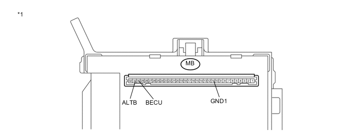
Text in Illustration *1 instrument panel junction block assembly - - -
Measure the voltage and resistance according to the value(s) in the table below.
Standard Voltage Tester Connection Condition Specified Condition MB-30 (BECU) - Body ground Always 11 to 14 V MB-31 (ALTB) - Body ground Always 11 to 14 V Standard Resistance Tester Connection Condition Specified Condition MB-11 (GND1) - Body ground Always Below 1 Ω
OK
PROCEED TO NEXT SUSPECTED AREA SHOWN IN PROBLEM SYMPTOMS TABLE Click here
NG
REPLACE INSTRUMENT PANEL JUNCTION BLOCK ASSEMBLY Click here
-