LIGHTING SYSTEM Engine Switch Illumination Circuit
DESCRIPTION
The illuminated entry system controls the engine switch illumination.
WIRING DIAGRAM
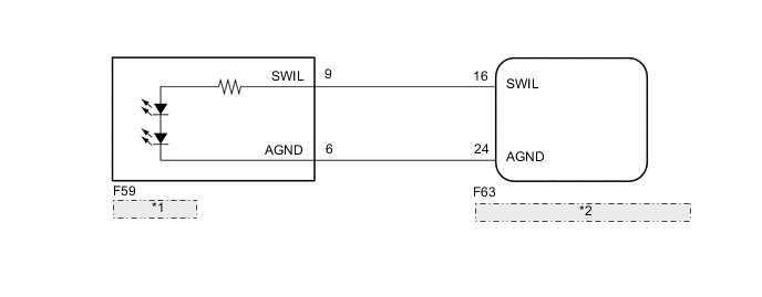
| *1 | ENGINE SWITCH |
| *2 | CERTIFICATION ECU (SMART KEY ECU ASSEMBLY) |
PROCEDURE
-
INSPECT ENGINE SWITCH
-
Remove the engine switch.
-
for 1NR-FE Click here
-
for 1NZ-FE Click here
-
for 1ND-TV Click here
-
-
Inspect the engine switch.
-
for 1NR-FE Click here
-
for 1NZ-FE Click here
-
for 1ND-TV Click here
Result Result Proceed to OK A NG
(for 1NR-FE)
B NG
(for 1NZ-FE)
C NG
(for 1ND-TV)
D -
B 
REPLACE ENGINE SWITCH Click here
C
REPLACE ENGINE SWITCH Click here
D
REPLACE ENGINE SWITCH Click here
A 
-
-
CHECK HARNESS AND CONNECTOR (ENGINE SWITCH - CERTIFICATION ECU)
-
Disconnect the F63 certification ECU (smart key ECU assembly) connector.
-
Measure the resistance according to the value(s) in the table below.
Standard Resistance (Check for Open) Tester Connection Condition Specified Condition F59-9 (SWIL) - F63-16 (SWIL) Always Below 1 Ω F59-6 (AGND) - F63-24 (AGND) Always Below 1 Ω Standard Resistance (Check for Short) Tester Connection Condition Specified Condition F59-9 (SWIL) - Body ground Always 10 kΩ or higher F59-6 (AGND) - Body ground Always 10 kΩ or higher
OK
REPLACE CERTIFICATION ECU (SMART KEY ECU ASSEMBLY)
NG
REPAIR OR REPLACE HARNESS OR CONNECTOR
-