ENGINE IMMOBILISER SYSTEM(w/o Entry and Start System), Diagnostic DTC:B279A
| DTC Code | DTC Name |
|---|---|
| B279A | Theft Deterrent System Communication Line High Fixation |
DESCRIPTION
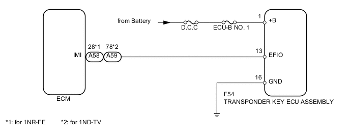
When the communication line (EFIO-IMI) between the transponder key ECU assembly and ECM is stuck on HI output, the ECM stores this DTC.
| DTC Code | DTC Detection Condition | Trouble Area | DTC Output Confirmation Operation |
|---|---|---|---|
| B279A | The communication line (EFIO-IMI) between the ECM and transponder key ECU assembly is stuck on HI output (1 trip detection logic*). |
|
Turn the ignition switch to ON and wait 6 seconds. |
-
*: Only output while a malfunction is present.
| Vehicle Condition when Malfunction Detected | Fail-safe Operation when Malfunction Detected |
|---|---|
| Engine cannot be started (initial ignition occurs and engine cranks, then ignition stops) | Engine cannot be started |
| DTC Code | Data List and Active Test |
|---|---|
| B279A | - |
WIRING DIAGRAM
CAUTION / NOTICE / HINT
Note
-
When replacing the transponder key ECU assembly or ECM, refer to the Service Bulletin.
-
Inspect the fuses for circuits related to this system before performing the following inspection procedure.
PROCEDURE
-
CLEAR DTC
-
Clear the DTCs Click here.
NEXT 
-
-
CHECK FOR DTC
-
Check for DTCs Click here.
OK DTC B279A is not output.
OK 
USE SIMULATION METHOD TO CHECK Click here
NG
-
-
CHECK HARNESS AND CONNECTOR (TRANSPONDER KEY ECU - ECM)
-
Disconnect the F54 transponder key ECU assembly connector.
-
Disconnect the A58*1 or A59*2 ECM connector.
-
Measure the resistance according to the value(s) in the table below.
Standard Resistance (Check for Open) Tester Connection Condition Specified Condition F54-13 (EFIO) - A58-28 (IMI)*1 Always Below 1 Ω F54-13 (EFIO) - A59-78 (IMI)*2 Always Below 1 Ω Standard Resistance (Check for Short) Tester Connection Condition Specified Condition F54-13 (EFIO) or A58-28 (IMI) - Body ground*1 Always 10 kΩ or higher F54-13 (EFIO) or A59-78 (IMI) - Body ground*2 Always 10 kΩ or higher -
Measure the voltage according to the value(s) in the table below.
Standard Voltage Tester Connection Condition Specified Condition A58-28 (IMI) - Body ground*1 Always Below 1 V A59-78 (IMI) - Body ground*2 Always Below 1 V
-
*1: for 1NR-FE
-
*2: for 1ND-TV
-
NG
REPAIR OR REPLACE HARNESS OR CONNECTOR
OK
-
-
CHECK TRANSPONDER KEY ECU ASSEMBLY (TERMINAL EFIO)
-
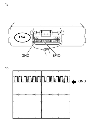
Text in Illustration *a Component with harness connected
(Transponder Key ECU Assembly)
*b Waveform Using an oscilloscope, check the waveform.
Measurement Condition Item Content Tester Connection F54-13 (EFIO) - F54-16 (GND) Tool Setting 10 V/DIV., 100 ms./DIV. Condition Ignition switch ON Tech Tips
-
The waveform shown in the illustration is an example for reference only. Noise, chattering, etc. are not shown.
-
If you forget to note the waveform, etc. and need to recheck it, disconnect and reconnect the ECM connector before rechecking it.
OK Waveform is output normally (refer to illustration). Result Result Proceed to Terminal EFIO stuck high (10 V) A Normal waveform (1NR-FE) B Normal waveform (1ND-TV) C -
B
REPLACE ECM Click here
C
REPLACE ECM Click here
A
-
-
REPLACE TRANSPONDER KEY ECU ASSEMBLY
-
Temporarily replace the transponder key ECU assembly with a new one (Refer to service Bulletin).
NEXT
-
-
REGISTER ECU - ECM COMMUNICATION ID
-
Register the ECU - ECM communication ID (Refer to service Bulletin).
NEXT
-
-
CHECK WHETHER ENGINE STARTS
-
Check that the engine starts with the key.
OK Engine starts normally. Result Result Proceed to OK A NG (1NR-FE) B NG (1ND-TV) C
A
END (TRANSPONDER KEY ECU WAS DEFECTIVE)
B
REPLACE ECM Click here
C
REPLACE ECM Click here
-