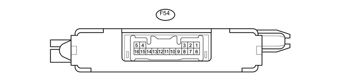
ENGINE IMMOBILISER SYSTEM(w/o Entry and Start System) TERMINALS OF ECU
-
CHECK TRANSPONDER KEY ECU ASSEMBLY
-
Disconnect the F54 transponder key ECU assembly connector.
-
Measure the resistance and voltage according to the value(s) in the table below.
Terminal No. (Symbol) Input/Output Wiring Color Terminal Description Condition Specified Condition Related Data List Item F54-1 (+B) - F54-5 (GND) Input Y - BR Battery Always 11 to 14 V +B F54-2 (IG) - F54-5 (GND) Input P - BR Ignition switch signal Ignition switch off Below 1 V IG SW Ignition switch ON 11 to 14 V F54-3 (KSW) - F54-5 (GND) Input BE - BR Unlock warning switch signal No key is in ignition key cylinder 10 kΩ or higher KEY SW/B2780 Key is in ignition key cylinder Below 1 Ω F54-5 (GND) - Body ground - BR - Body ground Ground Always Below 1 Ω - If the result is not as specified, there may be a malfunction on the wire harness side.
-
Reconnect the F54 transponder key ECU assembly connector.
-
Measure the voltage and check for pulses according to the value(s) in the table below.
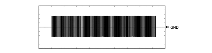
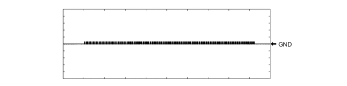
Terminal No. (Symbol) Input/Output Wiring Color Terminal Description Condition Specified Condition Related Data List Item F54-8 (IND) - F54-5 (GND) Output SB - BR Security indicator signal No key in ignition key cylinder, or 20 seconds elapsed after turning ignition switch to ACC or off (immobiliser system set) Pulse generation Immobiliser Key in ignition key cylinder (immobiliser system unset) Below 1 V F54-9 (D) - F54-5 (GND) Input/Output B - BR DLC3 communication Without communication Below 1 V - During communication Pulse generation F54-4 (ANT1) - F54-5 (GND) Input/Output L - BR Transponder key amplifier power source No key in ignition key cylinder 4 to 6 V - Within 3 seconds of inserting key into ignition key cylinder Pulse generation (See waveform 1) F54-15 (ANT2) - F54-5 (GND) Input/Output P - BR Transponder key amplifier communication signal No key in ignition key cylinder 4 to 6 V - Within 3 seconds of inserting key into ignition key cylinder Pulse generation (See waveform 2) F54-12 (EFII) - F54-5 (GND) Output LG - BR ECM input signal Ignition switch off 11 to 14 V - Check waveform within 3 seconds of starter operation and initial combustion, or within 3 seconds of ignition switch first being turned to ON after cable disconnected and reconnected to negative (-) battery terminal. Pulse generation (See waveform 3) F54-13 (EFIO) - F54-5 (GND) Input R - BR ECM output signal Ignition switch off Below 1 V - Check waveform within 3 seconds of starter operation and initial combustion, or within 3 seconds of ignition switch first being turned to ON after cable disconnected and reconnected to negative (-) battery terminal. Pulse generation (See waveform 4) If the result is not as specified, the transponder key ECU assembly may be malfunctioning.
-
Using an oscilloscope, check the waveform.
-
Waveform 1 (Reference)
-
Waveform 2 (Reference)
-
Waveform 3 (Reference)
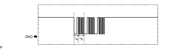
Text in Illustration *a Approximately 160 ms *b Approximately 270 ms -
Waveform 4 (Reference)
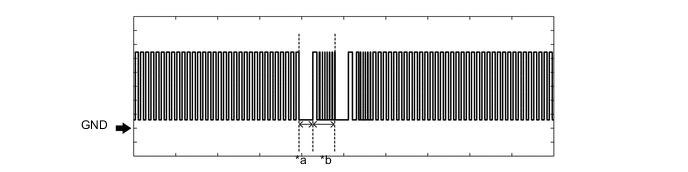
Text in Illustration *a Approximately 160 ms *b Approximately 270 ms
-
-
-
CHECK ECM (for 1NR-FE)
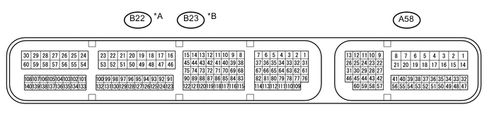
Text in Illustration *A for LHD *B for RHD
-
The values listed under "Specified Condition" are reference values. Because waterproof connectors are used for ECM, inspections can not be performed with the connectors connected.
-
Measure the voltage and check for pulses according to the value(s) in the table below.
for LHD Terminal No. (Symbol) Input/Output Wiring Color Terminal Description Condition Specified Condition Related Data List Item A58-1 (BATT) - B22-16 (E1) input Y - W-B Battery (for measuring battery voltage and for ECM memory) Always 11 to 14 V - A58-2 (+B) - B22-16 (E1) input B - W-B Power source for ECM Ignition switch ON 11 to 14 V - A58-3 (+B2) - B22-16 (E1) input B - W-B Power source for ECM Ignition switch ON 11 to 14 V - A58-46 (MREL) - B22-16 (E1) input GR - W-B EFI MAIN relay operation signal Ignition switch ON 11 to 14 V - B22-16 (E1) - Body ground - W-B - Body ground Ground Always Below 1 Ω - A58-29 (IMO) - B22-16 (E1) input W - W-B Transponder key ECU assembly communication input signal Ignition switch off 11 to 14 V - Check waveform within 3 seconds of starter operation and initial combustion, or within 3 seconds of ignition switch first being turned to ON after cable disconnected and reconnected to negative (-) battery terminal. Pulse generation (See waveform 1) A58-28 (IMI) - B22-16 (E1) output G - W-B Transponder key ECU assembly communication output signal Ignition switch off Below 1 V - Check waveform within 3 seconds of starter operation and initial combustion, or within 3 seconds of ignition switch first being turned to ON after cable disconnected and reconnected to negative (-) battery terminal. Pulse generation (See waveform 2) for RHD Terminal No. (Symbol) Input/Output Wiring Color Terminal Description Condition Specified Condition Related Data List Item A58-1 (BATT) - B23-16 (E1) input Y - W-B Battery (for measuring battery voltage and for ECM memory) Always 11 to 14 V - A58-2 (+B) - B23-16 (E1) input B - W-B Power source for ECM Ignition switch ON 11 to 14 V - A58-3 (+B2) - B23-16 (E1) input B - W-B Power source for ECM Ignition switch ON 11 to 14 V - A58-46 (MREL) - B23-16 (E1) input GR - W-B EFI MAIN relay operation signal Ignition switch ON 11 to 14 V - B23-16 (E1) - Body ground - W-B - Body ground Ground Always Below 1 Ω - A58-29 (IMO) - B23-16 (E1) input W - W-B Transponder key ECU assembly communication input signal Ignition switch off 11 to 14 V - Check waveform within 3 seconds of starter operation and initial combustion, or within 3 seconds of ignition switch first being turned to ON after cable disconnected and reconnected to negative (-) battery terminal. Pulse generation (See waveform 1) A58-28 (IMI) - B23-16 (E1) output G - W-B Transponder key ECU assembly communication output signal Ignition switch off Below 1 V - Check waveform within 3 seconds of starter operation and initial combustion, or within 3 seconds of ignition switch first being turned to ON after cable disconnected and reconnected to negative (-) battery terminal. Pulse generation (See waveform 2) If the result is not as specified, the transponder key ECU assembly may be malfunctioning.
-
Using an oscilloscope, check the waveform.
-
Waveform 1 (Reference)
Text in Illustration *a Approximately 160 ms *b Approximately 270 ms
-
*1: for LHD
-
*2: for RHD
-
-
Waveform 2 (Reference)
Text in Illustration *a Approximately 160 ms *b Approximately 270 ms
-
*1: for LHD
-
*2: for RHD
-
-
-
-
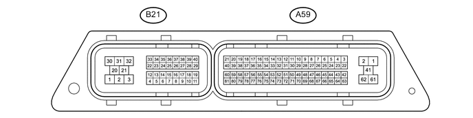
CHECK ECM (for 1ND-TV)
-
The values listed under "Specified Condition" are reference values. Because waterproof connectors are used for ECM, inspections can not be performed with the connectors connected.
-
Measure the voltage and check for pulses according to the value(s) in the table below.
Terminal No. (Symbol) Input/Output Wiring Color Terminal Description Condition Specified Condition Related Data List Item A59-23 (BATT) - A59-2 (E1) input V - W-B Battery (for measuring battery voltage and for ECM memory) Always 11 to 14 V - A59-1 (+B) - A59-2 (E1) input B - W-B Power source for ECM Ignition switch ON 11 to 14 V - A59-61 (+B2) - A59-2 (E1) input B - W-B Power source for ECM Ignition switch ON 11 to 14 V - A58-22 (MREL) - A59-2 (E1) input GR - W-B EFI MAIN relay operation signal Ignition switch ON 11 to 14 V - A59-2 (E1) - Body ground - W-B - Body ground Ground Always Below 1 Ω - A59-78 (IMO) - A59-2 (E1) input W - W-B Transponder key ECU assembly communication input signal Ignition switch off 11 to 14 V - Check waveform within 3 seconds of starter operation and initial combustion, or within 3 seconds of ignition switch first being turned to ON after cable disconnected and reconnected to negative (-) battery terminal. Pulse generation (See waveform 1) A59-77 (IMI) - A59-2 (E1) output G - W-B Transponder key ECU assembly communication output signal Ignition switch off Below 1 V - Check waveform within 3 seconds of starter operation and initial combustion, or within 3 seconds of ignition switch first being turned to ON after cable disconnected and reconnected to negative (-) battery terminal. Pulse generation (See waveform 2) If the result is not as specified, the transponder key ECU assembly may be malfunctioning.
-
Using an oscilloscope, check the waveform.
-
Waveform 1 (Reference)
Text in Illustration *a Approximately 160 ms *b Approximately 270 ms -
Waveform 2 (Reference)
Text in Illustration *a Approximately 160 ms *b Approximately 270 ms
-
-