ENGINE IMMOBILISER SYSTEM(w/o Entry and Start System) Security Indicator Light Does not Blink
DESCRIPTION
-
When the engine immobiliser system is set, the security indicator light blinks continuously, but does not illuminate if the engine immobiliser system is not set.
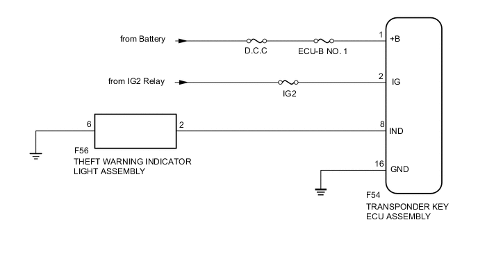
WIRING DIAGRAM
CAUTION / NOTICE / HINT
Note
-
Inspect the fuses for circuits related to this system before performing the following inspection procedure.
-
When replacing the transponder key ECU assembly, refer to Registration.
PROCEDURE
-
CHECK FOR DTC
-
Check for DTCs Click here.
OK DTC is not output.
NG 
Go to DIAGNOSTIC TROUBLE CODE CHART Click here
OK 
-
-
PERFORM ACTIVE TEST USING INTELLIGENT TESTER (SECURITY INDICATOR LIGHT)
-
Check that the theft warning indicator light assembly illuminates when operating it with the Active Test Click here.
Immobiliser Tester Display Test Part Control Range Diagnostic Note Security Indicator Security indicator light ON/OFF The test is possible when the following condition is met:
-
The key is in the ignition key cylinder.
OK Theft warning indicator light assembly (security indicator light) can be turned on and off using the intelligent tester. -
NG 
CHECK HARNESS AND CONNECTOR (THEFT WARNING INDICATOR LIGHT ASSEMBLY - TRANSPONDER KEY ECU AND BODY GROUND) Click here
OK
-
-
READ VALUE USING INTELLIGENT TESTER (ENGINE IMMOBILISER SYSTEM STATUS)
-
Turn the ignition switch off.
Tech Tips
When using the intelligent tester with the ignition switch off to troubleshoot: Connect the intelligent tester to the DLC3 and turn a courtesy light switch on and off at intervals of 1.5 seconds until communication between the intelligent tester and vehicle begins.
-
Using the intelligent tester, read the Data List Click here.
Immobiliser Tester Display Measurement Item/Range Normal Condition Diagnostic Note Immobiliser Engine immobiliser system status determined by transponder key ECU assembly / Set or Unset Set: Engine immobiliser set (engine start prohibited [no key in ignition key cylinder])
Unset: Engine immobiliser unset (engine start permitted [key inserted in ignition key cylinder])
When the engine immobiliser system does not change to the unset state, this item can be used to determine if the cause is the transponder key ECU assembly.
OK
REPLACE TRANSPONDER KEY ECU ASSEMBLY
NG
CHECK HARNESS AND CONNECTOR (TRANSPONDER KEY ECU - BATTERY AND BODY GROUND) Click here
-
-
CHECK HARNESS AND CONNECTOR (THEFT WARNING INDICATOR LIGHT ASSEMBLY - TRANSPONDER KEY ECU AND BODY GROUND)
-
Disconnect the F56 theft warning indicator light assembly connector.
-
Disconnect the F54 transponder key ECU assembly connector.
-
Measure the resistance according to the value(s) in the table below.
Standard Resistance (Check for Open) Tester Connection Condition Specified Condition F56-2 - F54-8 (IND) Always Below 1 Ω F56-6 - Body ground Always Below 1 Ω Standard Resistance (Check for Short) Tester Connection Condition Specified Condition F56-2 or F54-8 (IND) - Body ground Always 10 kΩ or higher
NG
REPAIR OR REPLACE HARNESS OR CONNECTOR
OK
-
-
INSPECT THEFT WARNING INDICATOR LIGHT ASSEMBLY
-
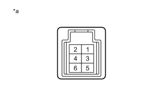
Text in Illustration *a Component without harness connected
(Theft Warning Indicator Light Assembly)
Remove the theft warning indicator light assembly.
-
Apply battery voltage to the theft warning indicator light assembly and check that the illumination comes on.
OK Measurement Connection Specified Condition Battery positive (+) → Terminal 2
Battery negative (-) → Terminal 6
Illumination comes on
OK
REPLACE TRANSPONDER KEY ECU ASSEMBLY
NG
REPLACE THEFT WARNING INDICATOR LIGHT ASSEMBLY
-
-
CHECK HARNESS AND CONNECTOR (TRANSPONDER KEY ECU - BATTERY AND BODY GROUND)
-
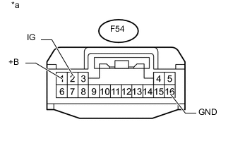
Text in Illustration *a Front view of wire harness connector
(to Transponder Key ECU Assembly)
Disconnect the F54 transponder key ECU assembly connector.
-
Measure the resistance according to the value(s) in the table below.
Standard Resistance Tester Connection Condition Specified Condition F54-16 (GND) - Body ground Always Below 1 Ω -
Measure the voltage according to the value(s) in the table below.
Standard Voltage Tester Connection Switch Condition Specified Condition F54-1 (+B) - Body ground Always 11 to 14 V F54-2 (IG) - Body ground Ignition switch off Below 1 V Ignition switch ON 11 to 14 V
OK
REPLACE TRANSPONDER KEY ECU ASSEMBLY
NG
REPAIR OR REPLACE HARNESS OR CONNECTOR
-