ENGINE IMMOBILISER SYSTEM(w/ Entry and Start System), Diagnostic DTC:B2799
| DTC Code | DTC Name |
|---|---|
| B2799 | Engine Immobiliser System Malfunction |
DESCRIPTION
When there are communication malfunctions between the ECM and ID code box (immobiliser code ECU)*1 or certification ECU (smart key ECU assembly)*2, or when the communication ID codes do not match, the ECM stores this DTC.
| DTC Code | DTC Detection Condition | Trouble Area | DTC Output Confirmation Operation |
|---|---|---|---|
| B2799 | Either condition is met (1 trip detection logic*3):
|
|
Either condition is met:
|
-
*1: except 1NZ-FE
-
*2: for 1NZ-FE
-
*3: Only output while a malfunction is present.
-
*4: for CVT
-
*5: for Manual Transaxle
| Vehicle Condition when Malfunction Detected | Fail-safe Operation when Malfunction Detected |
|---|---|
| Engine cannot be started | - |
| DTC Code | Data List and Active Test |
|---|---|
| B2799 | - |
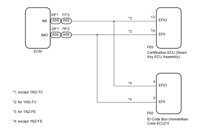
WIRING DIAGRAM
CAUTION / NOTICE / HINT
Note
-
When replacing the ID code box (immobiliser code ECU)*1 or certification ECU (smart key ECU assembly)*2, refer to the Service Bulletin.
-
The fixed 12 V power source voltage in the ECM is output through a resistance from terminal IMI. The ID code box (immobiliser code ECU)*1 or certification ECU (smart key ECU assembly)*2 grounds or does not ground this power source voltage accordingly.
-
The fixed 12 V power source voltage in the ID code box (immobiliser code ECU)*1 or certification ECU (smart key ECU assembly)*2 is output through a resistance from terminal EFII. The ECM grounds or does not ground this power source voltage accordingly.
-
After performing repairs, perform the operation that fulfills the DTC output confirmation operation, and then confirm that no DTCs are output again.
-
*1: except 1NZ-FE
-
*2: for 1NZ-FE
Tech Tips
When DTC B2799 and the certification ECU (smart key ECU assembly) DTC are output simultaneously, first perform troubleshooting for the certification ECU (smart key ECU assembly) DTC.
PROCEDURE
-
CLEAR DTC
-
Clear the DTCs Click here.
NEXT 
-
-
CHECK FOR DTC
-
Check for DTCs Click here.
Tech Tips
Before checking for DTCs, perform the "DTC Output Confirmation Operation" procedure.
OK DTC B2799 is not output.
OK 
USE SIMULATION METHOD TO CHECK Click here
NG
-
-
CHECK VEHICLE CONDITION
-
Check the vehicle condition.
Result Proceed to except 1NZ-FE A for 1NZ-FE B
B 
CHECK CERTIFICATION ECU (SMART KEY ECU ASSEMBLY) (TERMINAL EFII) Click here
A
-
-
CHECK ID CODE BOX (IMMOBILISER CODE ECU) (TERMINAL EFII)
-
Using an oscilloscope, check the waveform.
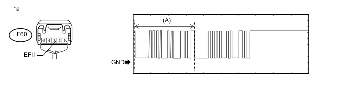
Text in Illustration *a Component with harness connected
(ID Code Box [Immobiliser Code ECU])
- - Measurement Condition Item Content Tester Connection F60-3 (EFII) - Body ground Tool Setting 2 V/DIV., 200 ms./DIV. Condition Within 3 seconds of engine start or within 3 seconds of engine switch turned on (IG) after battery cable disconnected and reconnected Tech Tips
The waveform shown in the illustration is an example for reference only. Noise, chattering, etc. are not shown.
OK Waveform is output normally (refer to illustration). Result Result Proceed to Normal waveform A Waveform (A) has abnormal wavelength or shape B Terminal EFII stuck high (12 V) Terminal EFII stuck low (2.4 V or less) C
B
REPLACE ECM Click here
C
CHECK ECM (INPUT WAVEFORM) Click here
A
-
-
CHECK ID CODE BOX (IMMOBILISER CODE ECU) (TERMINAL EFIO)
-
Using an oscilloscope, check the waveform.
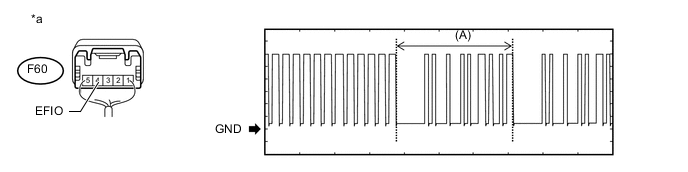
Text in Illustration *a Component with harness connected
(ID Code Box [Immobiliser Code ECU])
- - Measurement Condition Item Content Tester Connection F60-4 (EFIO) - Body ground Tool Setting 2 V/DIV., 200 ms./DIV. Condition Within 3 seconds of engine start or within 3 seconds of engine switch turned on (IG) after battery cable disconnected and reconnected Tech Tips
The waveform shown in the illustration is an example for reference only. Noise, chattering, etc. are not shown.
OK Waveform is output normally (refer to illustration). Result Result Proceed to Normal waveform A Waveform (A) not output, or has abnormal wavelength or shape B
B
REPLACE ID CODE BOX (IMMOBILISER CODE ECU) Click here
A
-
-
REGISTER RECOGNITION CODES
-
Register the recognition codes in the ECUs (Refer to Service Bulletin).
NEXT
-
-
REGISTER ECU COMMUNICATION ID
-
Register the ECU communication ID (Refer to Service Bulletin).
-
Check that the engine can be started with a registered electrical key transmitter.
OK Engine can be started with a registered electrical key transmitter.
OK
END (ECU COMMUNICATION ID IS NOT REGISTERED CORRECTLY)
NG
-
-
REPLACE ECM
-
Temporarily replace the ECM with a new one.
-
for 1NR-FE Click here
-
for 1ND-TV Click here
-
NEXT
-
-
CLEAR DTC
-
Clear the DTCs Click here.
NEXT
-
-
CHECK FOR DTC
-
Check for DTCs Click here.
Tech Tips
Before checking for DTCs, perform the "DTC Output Confirmation Operation" procedure.
OK DTC is not output.
OK
END (ECM IS DEFECTIVE)
NG
GO TO DIAGNOSTIC TROUBLE CODE CHART Click here
-
-
CHECK ECM (INPUT WAVEFORM)
-
Disconnect the A58*1 or A59*2 ECM connector.
-
*1: for 1NR-FE
-
*2: for 1ND-TV
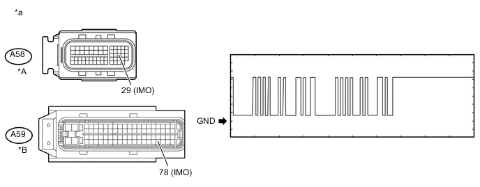
Text in Illustration *A for 1NR-FE *B for 1ND-TV *a Front view of wire harness connector
(to ECM)
- - -
-
Using an oscilloscope, check the waveform.
Tech Tips
Perform this inspection on the ECM side.
Measurement Condition Item Content Tester Connection A58-29 (IMO) - Body ground*1
A59-78 (IMO) - Body ground*2
Tool Setting 2 V/DIV., 200 ms./DIV. Condition Within 3 seconds of engine start or within 3 seconds of engine switch turned on (IG) after battery cable disconnected and reconnected
-
*1: for 1NR-FE
-
*2: for 1ND-TV
Tech Tips
The waveform shown in the illustration is an example for reference only. Noise, chattering, etc. are not shown.
OK Waveform is output normally (refer to illustration). Result Result Proceed to NG A OK B -
B
REPLACE ECM Click here
A
-
-
CHECK HARNESS AND CONNECTOR (ID CODE BOX (IMMOBILISER CODE ECU) - ECM AND BODY GROUND)
-
Disconnect the F60 ID code box (immobiliser code ECU) connector.
-
Disconnect the A58 ECM connector.
-
Measure the resistance according to the value(s) in the table below.
Standard Resistance (Check for Open) Tester Connection Condition Specified Condition F60-3 (EFII) - A58-29 (IMO) Always Below 1 Ω Standard Resistance (Check for Short) Tester Connection Condition Specified Condition F60-3 (EFII) or A58-29 (IMO) - Body ground Always 10 kΩ or higher
NG
REPAIR OR REPLACE HARNESS OR CONNECTOR
OK
-
-
REPLACE ID CODE BOX (IMMOBILISER CODE ECU)
-
Replace the ID code box (immobiliser code ECU) with a new one (Refer to Service Bulletin).
NEXT
-
-
CLEAR DTC
-
Clear the DTCs Click here.
-
Register the recognition codes in the ECUs (Refer to Service Bulletin).
-
Register the ECU communication ID (Refer to Service Bulletin).
NEXT
-
-
CHECK FOR DTC
-
Check for DTCs Click here.
Tech Tips
Before checking for DTCs, perform the "DTC Output Confirmation Operation" procedure.
OK DTC is not output.
OK
END (ID CODE BOX [IMMOBILISER CODE ECU] IS DEFECTIVE)
NG
GO TO DIAGNOSTIC TROUBLE CODE CHART Click here
-
-
REPLACE ECM
-
Temporarily replace the ECM with a new one.
-
for 1NR-FE Click here
-
for 1ND-TV Click here
-
NEXT
-
-
CLEAR DTC
-
Clear the DTCs Click here.
NEXT
-
-
CHECK FOR DTC
-
Check for DTCs Click here.
Tech Tips
Before checking for DTCs, perform the "DTC Output Confirmation Operation" procedure.
OK DTC is not output.
OK
END (ECM IS DEFECTIVE)
NG
GO TO DIAGNOSTIC TROUBLE CODE CHART Click here
-
-
CHECK CERTIFICATION ECU (SMART KEY ECU ASSEMBLY) (TERMINAL EFII)
-
Using an oscilloscope, check the waveform.
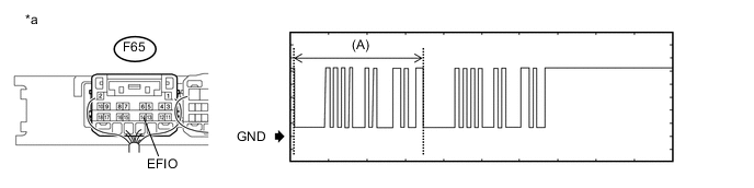
Text in Illustration *a Component with harness connected
(Certification ECU [Smart Key ECU Assembly])
- - Measurement Condition Item Content Tester Connection F65-14 (EFII) - Body ground Tool Setting 2 V/DIV., 200 ms./DIV. Condition Within 3 seconds of engine start or within 3 seconds of engine switch turned on (IG) after battery cable disconnected and reconnected Tech Tips
The waveform shown in the illustration is an example for reference only. Noise, chattering, etc. are not shown.
OK Waveform is output normally (refer to illustration). Result Result Proceed to Normal waveform A Waveform (A) has abnormal wavelength or shape B Terminal EFII stuck high (12 V) Terminal EFII stuck low (2.4 V or less) C
B
REPLACE ECM Click here
C
CHECK CERTIFICATION ECU (SMART KEY ECU ASSEMBLY) (TERMINAL IMO) Click here
A
-
-
CHECK CERTIFICATION ECU (SMART KEY ECU ASSEMBLY) (TERMINAL EFIO)
-
Using an oscilloscope, check the waveform.
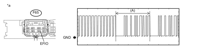
Text in Illustration *a Component with harness connected
(Certification ECU [Smart Key ECU Assembly])
- - Measurement Condition Item Content Tester Connection F65-13 (EFIO) - Body ground Tool Setting 2 V/DIV., 200 ms./DIV. Condition Within 3 seconds of engine start or within 3 seconds of engine switch turned on (IG) after battery cable disconnected and reconnected Tech Tips
The waveform shown in the illustration is an example for reference only. Noise, chattering, etc. are not shown.
OK Waveform is output normally (refer to illustration). Result Result Proceed to Normal waveform A Waveform (A) not output, or has abnormal wavelength or shape B
B
END (CERTIFICATION ECU IS DEFECTIVE)
A
-
-
REGISTER RECOGNITION CODES
-
Register the recognition codes in the ECUs (Refer to Service Bulletin).
NEXT
-
-
REGISTER ECU COMMUNICATION ID
-
Register the ECU communication ID (Refer to Service Bulletin).
-
Check that the engine can be started with a registered electrical key transmitter.
OK Engine can be started with a registered electrical key transmitter.
OK
END (ECU COMMUNICATION ID IS NOT REGISTERED CORRECTLY)
NG
-
-
REPLACE ECM
-
Temporarily replace the ECM with a new one Click here.
NEXT
-
-
CLEAR DTC
-
Clear the DTCs Click here.
NEXT
-
-
CHECK FOR DTC
-
Check for DTCs Click here.
Tech Tips
Before checking for DTCs, perform the "DTC Output Confirmation Operation" procedure.
OK DTC is not output.
OK
END (ECM IS DEFECTIVE)
NG
GO TO DIAGNOSTIC TROUBLE CODE CHART Click here
-
-
CHECK CERTIFICATION ECU (SMART KEY ECU ASSEMBLY) (TERMINAL IMO)
-
Disconnect the A58 ECM connector.
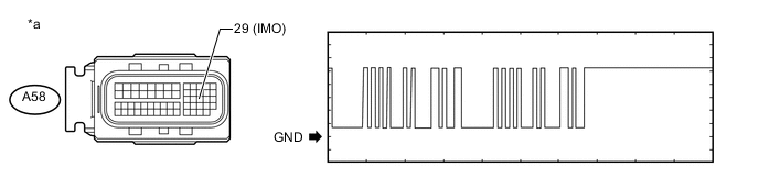
Text in Illustration *a Front view of wire harness connector
(to ECM)
- - -
Using an oscilloscope, check the waveform.
Tech Tips
Perform this inspection on the ECM side.
Measurement Condition Item Content Tester Connection A58-29 (IMO) - Body ground Tool Setting 2 V/DIV., 200 ms./DIV. Condition Within 3 seconds of engine start or within 3 seconds of engine switch turned on (IG) after battery cable disconnected and reconnected Tech Tips
The waveform shown in the illustration is an example for reference only. Noise, chattering, etc. are not shown.
OK Waveform is output normally (refer to illustration). Result Result Proceed to Terminal IMO low output (2.4 V or less) A Terminal IMO high output (12 V) B
B
REPLACE ECM Click here
A
-
-
CHECK HARNESS AND CONNECTOR (CERTIFICATION ECU (SMART KEY ECU ASSEMBLY) - ECM AND BODY GROUND)
-
Disconnect the F65 certification ECU (smart key ECU assembly) connector.
-
Disconnect the A58 ECM connector.
-
Measure the resistance according to the value(s) in the table below.
Standard Resistance (Check for Open) Tester Connection Condition Specified Condition F65-14 (EFII) - A58-29 (IMO) Always Below 1 Ω Standard Resistance (Check for Short) Tester Connection Condition Specified Condition F65-14 (EFII) or A58-29 (IMO) - Body ground Always 10 kΩ or higher
NG
REPAIR OR REPLACE HARNESS OR CONNECTOR
OK
-
-
REPLACE CERTIFICATION ECU (SMART KEY ECU ASSEMBLY)
-
Replace the certification ECU (smart key ECU assembly) with a new one (Refer to Service Bulletin).
NEXT
-
-
CLEAR DTC
-
Clear the DTCs Click here.
NEXT
-
-
CHECK FOR DTC
-
Check for DTCs Click here.
Tech Tips
Before checking for DTCs, perform the "DTC Output Confirmation Operation" procedure.
OK DTC is not output.
OK
END (CERTIFICATION ECU IS DEFECTIVE)
NG
GO TO DIAGNOSTIC TROUBLE CODE CHART Click here
-
-
REPLACE ECM
-
Temporarily replace the ECM with a new one Click here.
NEXT
-
-
CLEAR DTC
-
Clear the DTCs Click here.
NEXT
-
-
CHECK FOR DTC
-
Check for DTCs Click here.
Tech Tips
Before checking for DTCs, perform the "DTC Output Confirmation Operation" procedure.
OK DTC is not output.
OK
END (ECM IS DEFECTIVE)
NG
GO TO DIAGNOSTIC TROUBLE CODE CHART Click here
-