ENTRY AND START SYSTEM(for Start Function) Power Source Mode does not Change to ON (IG)
DESCRIPTION
When the engine switch is pushed with the electrical key transmitter in the cabin, the certification ECU (smart key ECU assembly) receives signals to switch the power source mode.
Use this troubleshooting procedure when the power source mode does not change to on (IG) but does change to on (ACC).
Tech Tips
When the battery cable is disconnected and reconnected, the power source mode returns to the mode it was in before the battery cable was disconnected.
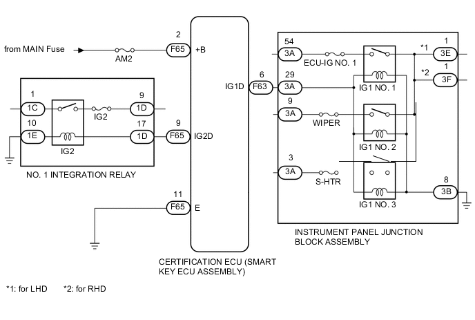
WIRING DIAGRAM
CAUTION / NOTICE / HINT
Note
-
When using the intelligent tester with the engine switch off, perform either of the following: 1) Turn a courtesy light switch on and off at intervals of 1.5 seconds or less until communication between the intelligent tester and vehicle begins, or 2) connect the intelligent tester to the vehicle and select "MANUAL" from the initial screen on the intelligent tester, and then select "KEY REGIST" under Model Code.
-
Make sure that no DTCs are output. If any DTCs are output, proceed to the Diagnostic Trouble Code Chart Click here.
-
The entry and start system uses multiplex communication. First perform the inspections in "How to Proceed with Troubleshooting" to confirm that there are no communication malfunctions before proceeding with troubleshooting Click here.
-
If the entry and start system is disabled through the customize function, enable the system before performing troubleshooting Click here.
-
Inspect the fuses of circuits related to this system before performing the following inspection procedure.
-
After completing repairs, confirm that the problem does not occur.
Note
Inspect the fuses for circuits related to this system before performing the following inspection procedure.
PROCEDURE
-
CHECK HARNESS AND CONNECTOR (POWER SOURCE)
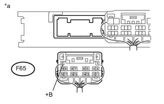
Text in Illustration *a Rear view of harness connected
(to Certification ECU (Smart Key ECU Assembly))
-
Disconnect the F65 certification ECU (smart key ECU assembly) connector.
-
Measure the voltage according to the value(s) in the table below.
Standard Voltage Tester Connection Condition Specified Condition F65-2 (+B) - Body ground Always 9.5 to 16 V
NG 
REPAIR OR REPLACE HARNESS OR CONNECTOR IN CIRCUIT CONNECTED TO POWER SOURCE
OK 
-
-
CHECK HARNESS AND CONNECTOR (INSTRUMENT PANEL JUNCTION BLOCK - NO. 1 INTEGRATION RELAY)
-
Disconnect the F65 certification ECU (smart key ECU assembly) connector.
-
Disconnect the 1D and 1E No. 1 integration relay connectors.
-
Measure the resistance according to the value(s) in the table below.
Standard Resistance Tester Connection Condition Specified Condition F65-9 (IG2D) - 1D-17 Always Below 1 Ω 1E-10 - Body ground Always Below 1 Ω
NG
REPAIR OR REPLACE HARNESS OR CONNECTOR
OK
-
-
INSPECT NO. 1 INTEGRATION RELAY
-
Remove the No. 1 integration relay.
-
for 1NZ-FE Click here
-
for 1NR-FE Click here
-
for 1ND-TV Click here
-
-
Inspect the No. 1 integration relay.
-
for 1NZ-FE Click here
-
for 1NR-FE Click here
-
for 1ND-TV Click here
Result Result Proceed to OK A NG (for 1NZ-FE) B NG (for 1NR-FE) C NG (for 1ND-TV) D -
B
REPLACE NO. 1 INTEGRATION RELAY Click here
C
REPLACE NO. 1 INTEGRATION RELAY Click here
D
REPLACE NO. 1 INTEGRATION RELAY Click here
A
-
-
CHECK HARNESS AND CONNECTOR (INSTRUMENT PANEL JUNCTION BLOCK - CERTIFICATION ECU)
-
Disconnect the F63 certification ECU (smart key ECU assembly) connector.
-
Disconnect the 3A and 3B instrument panel junction block assembly connectors.
-
Measure the resistance according to the value(s) in the table below.
Standard Resistance Tester Connection Connection Specified Condition F63-6 (IG1D) - 3A-29 Always Below 1 Ω 3B-8 - Body ground Always Below 1 Ω
NG
REPAIR OR REPLACE HARNESS OR CONNECTOR
OK
-
-
INSPECT INSTRUMENT PANEL JUNCTION BLOCK ASSEMBLY
-
Remove the instrument panel junction block assembly Click here.
-
Remove the main body ECU (multiplex network body ECU) from the instrument panel junction block assembly.
-
Measure the resistance according to the value(s) in the table below.
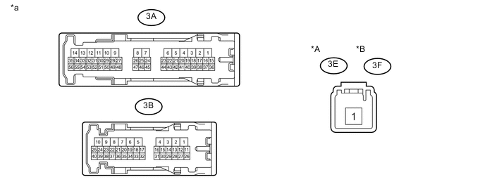
Text in Illustration *A for LHD *B for RHD *a Component without harness connected
(Instrument Panel Junction Block Assembly)
- - Standard Resistance for LHD Tester Connection Connection Specified Condition 3E-1 - 3A-54 Connect a positive (+) lead from the battery → 3A-29
Connect a negative (-) lead from the battery → 3B-8
Below 1 Ω Not connect a positive (+) lead from the battery → 3A-29
Not connect a negative (-) lead from the battery → 3B-8
10 kΩ or higher for RHD Tester Connection Connection Specified Condition 3F-1 - 3A-54 Connect a positive (+) lead from the battery → 3A-29
Connect a negative (-) lead from the battery → 3B-8
Below 1 Ω Not connect a positive (+) lead from the battery → 3A-29
Not connect a negative (-) lead from the battery → 3B-8
10 kΩ or higher
NG
REPLACE INSTRUMENT PANEL JUNCTION BLOCK ASSEMBLY Click here
OK
-
-
INSPECT CERTIFICATION ECU (SMART KEY ECU ASSEMBLY)
-
Reconnect the F65 certification ECU (smart key ECU assembly) connector.
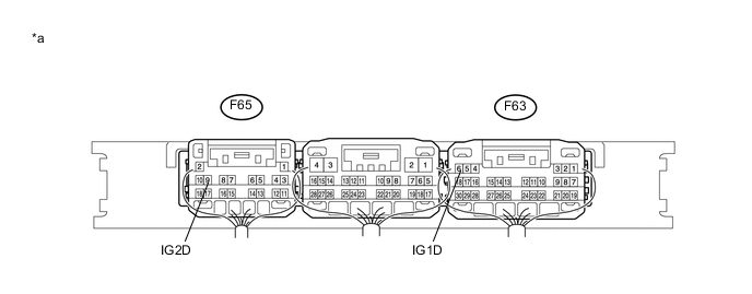
*a Component with harness connected
(Certification ECU (Smart Key ECU Assembly))
- - -
Measure the voltage according to the value(s) in the table below.
Standard Voltage Tester Connection Switch Condition Specified Condition F63-6 (IG1D) - Body ground Engine switch on (ACC) Below 1 V Engine switch on (IG) 9 V or higher F65-9 (IG2D) - Body ground Engine switch on (ACC) Below 1 V Engine switch on (IG) 9 V or higher
OK
CHECK RELAY CONTACT SIDE CIRCUIT
NG
REPLACE CERTIFICATION ECU (SMART KEY ECU ASSEMBLY)
-