ENTRY AND START SYSTEM(for Entry Function) Room Oscillator does not Recognize Key
DESCRIPTION
If the room antenna assembly does not recognize a key, one of the following may be the cause: 1) communication between the No. 1 indoor electrical key antenna assembly (front floor) and key cannot be performed; or 2) communication between the No. 2 indoor electrical key antenna assembly (inside luggage) and key cannot be performed.
WIRING DIAGRAM
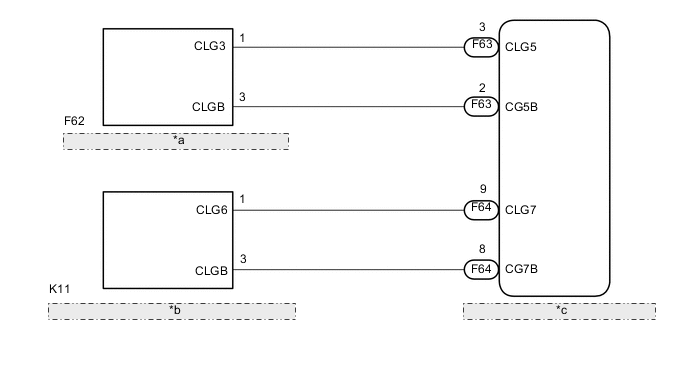
| *a | NO. 1 INDOOR ELECTRICAL KEY ANTENNA ASSEMBLY (Front Floor) |
| *b | NO. 2 INDOOR ELECTRICAL KEY ANTENNA ASSEMBLY (Inside Luggage) |
| *c | CERTIFICATION ECU (SMART KEY ECU ASSEMBLY) |
CAUTION / NOTICE / HINT
Note
-
The entry and start system (for entry function) uses a multiplex communication system (LIN communication system) and CAN communication system. Inspect the communication function by following How to Proceed with Troubleshooting Click here. Troubleshoot the entry and start system (for entry function) after confirming that the communication system is functioning properly.
-
When using the intelligent tester with the engine switch off to troubleshoot: Connect the intelligent tester to the DLC3, and turn a courtesy light switch on and off at 1.5-second intervals until communication between the tester and vehicle begins.
-
Before replacing the certification ECU (smart key ECU assembly), refer to the entry and start system (for entry function) Click here.
-
After repair, confirm DTC not reoccur with performing the "DTC Output Confirmation Operation".
-
Indoor electrical key antenna assembly have an antenna coil between each two CLG terminals.
Tech Tips
Check that the entry cancel function, which is one of the customizing settings of the entry and start system, is not set Click here.
PROCEDURE
-
CHECK WIRELESS DOOR LOCK CONTROL SYSTEM (OPERATION)
-
Check that the wireless door lock function operate normally Click here.
OK Wireless door lock functions operate normally.
NG 
GO TO ENTRY AND START SYSTEM (for Entry Function) Click here
OK 
-
-
CHECK ENTRY AND START SYSTEM (for Start Function)
-
Remove the battery of the electrical key transmitter Click here.
-
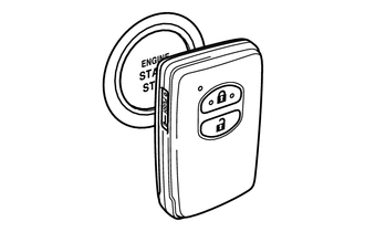
With the brake pedal*1 or clutch pedal*2 depressed, hold the electrical key transmitter touch the engine switch while facing the logo side of the electrical key transmitter to the engine switch.
-
*1: for CVT or Multi-mode Manual Transaxle
-
*2: for Manual Transaxle
-
-
When operating the engine switch, check whether the engine starts.
Tech Tips
-
When the electrical key transmitter cannot be verified even though it is within the specified range, the power source mode changes check can be performed by removing the transmitter battery from the electrical key transmitter and holding the transmitter close to the engine switch.
-
When performing the check, if the engine can be started, there is a problem with key certification inside the vehicle.
OK Engine starts. -
NG
GO TO ENTRY AND START SYSTEM (for Start Function) Click here
OK
-
-
CHECK WAVE ENVIRONMENT
-
Install the battery to the electrical key transmitter Click here.
-
Bring the electrical key transmitter near the No. 1 indoor electrical key antenna assembly (front floor), and check that the engine can be started.
Note
If the key is brought within 0.2 m (0.656 ft.) of the No. 1 indoor electrical key antenna assembly (front floor), communication is not possible.
-
Bring the electrical key transmitter near the No. 2 indoor electrical key antenna assembly (inside luggage), and check that the engine can be started*.
*: If the customize setting for Ignition Available Area is not set to All, the engine will not start. Before performing this inspection, check that All has been selected Click here.
Note
If the key is brought within 0.2 m (0.656 ft.) of the No. 2 indoor electrical key antenna assembly (inside luggage), communication is not possible.
Tech Tips
-
When the electrical key transmitter is brought near the No. 2 indoor electrical key antenna assembly, the possibility of wave interference decreases, and it can be determined if wave interference is causing the problem symptom.
-
If the operation is normal, the possibility of wave interference is high. Also, added vehicle components may cause wave interference. If installed, remove them and perform the operation check.
OK The engine starts. -
OK
AFFECTED BY WAVE INTERFERENCE
NG
-
-
PERFORM KEY DIAGNOSTIC MODE INSPECTION
-
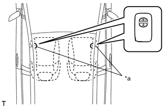
Text in Illustration *a Inspection point Diagnostic mode inspection (No. 1 indoor electrical key antenna assembly (front floor))
Note
Perform this check with the vehicle is stopped.
-
Connect the intelligent tester to the DLC3.
-
Turn the engine switch on (IG).
-
Turn the intelligent tester on.
-
Enter the following menus: Body / Entry & Start / Key Communication Check / Overhead + Front Room.
-
When the electrical key transmitter is in the position shown in the illustration, check that the wireless door lock buzzer sounds.
-
-
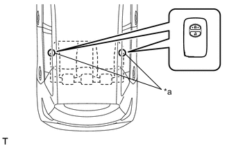
Text in Illustration *a Inspection point Diagnostic mode inspection (No. 2 indoor electrical key antenna assembly (inside luggage))
Note
Perform this check with the vehicle is stopped.
-
Connect the intelligent tester to the DLC3.
-
Turn the engine switch on (IG).
-
Turn the intelligent tester on.
-
Enter the following menus: Body / Entry & Start / Key Communication Check / Overhead + Back Door (inside).
-
When the electrical key transmitter is in the position shown in the illustration, check that the wireless door lock buzzer sounds.
Tech Tips
-
If the buzzer sounds, it can be determined that the vehicle interior transmitters are operating normally.
-
It is possible to check which indoor electrical key antenna assembly (front floor or inside luggage) is operating by the sounding of the buzzer.
-
If the buzzer does not sound for any indoor electrical key antenna assemblies, the certification ECU (smart key ECU assembly) circuit may have a malfunction.
Result Result Proceed to Front side operation fails A Inside luggage operation fails B -
-
B 
CHECK HARNESS AND CONNECTOR (CERTIFICATION ECU - NO. 2 INDOOR ELECTRICAL KEY ANTENNA) Click here
A
-
-
CHECK HARNESS AND CONNECTOR (CERTIFICATION ECU - NO. 1 INDOOR ELECTRICAL KEY ANTENNA)
-
Disconnect the F63 certification ECU (smart key ECU assembly) connector.
-
Disconnect the F62 No. 1 indoor electrical key antenna assembly (front floor) connector.
-
Measure the resistance according to the value(s) in the table below.
Standard Resistance (Check for Open) Tester Connection Condition Specified Condition F63-3 (CLG5) - F62-1 (CLG3) Always Below 1 Ω F63-2 (CG5B) - F62-3 (CLGB) Always Below 1 Ω Standard Resistance (Check for Short) Tester Connection Condition Specified Condition F63-3 (CLG5) - Body ground Always 10 kΩ or higher F62-1 (CLG3) - Body ground Always 10 kΩ or higher F63-2 (CG5B) - Body ground Always 10 kΩ or higher F62-3 (CLGB) - Body ground Always 10 kΩ or higher
NG
REPAIR OR REPLACE HARNESS OR CONNECTOR
OK
-
-
INSPECT CERTIFICATION ECU (SMART KEY ECU ASSEMBLY)
-
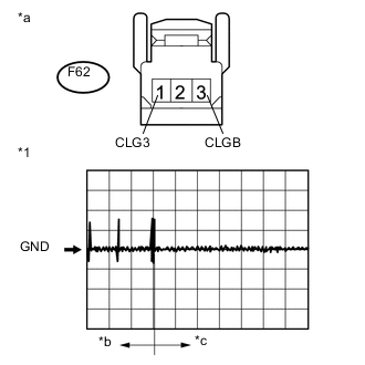
Text in Illustration *1 Waveform *a Front view of wire harness connector
(to No. 1 Indoor Electrical Key Antenna Assembly (front floor))
*b Door is open and then closed for 30 seconds *c From approximately 30 seconds after door is closed Reconnect the F63 certification ECU (smart key ECU assembly) connector.
-
Using an oscilloscope, check the waveform.
Standard Tester Connection Condition Tool Setting Specified Condition F62-1 (CLG3) - F62-3 (CLGB)
-
Engine switch off
-
Door is open
-
Door is closed
-
30 seconds elapse
-
Electrical key transmitter not inside vehicle
2 V/DIV., 500 ms/DIV. Pulse generation (See waveform) -
NG
REPLACE CERTIFICATION ECU (SMART KEY ECU ASSEMBLY)
OK
-
-
REPLACE NO. 1 INDOOR ELECTRICAL KEY ANTENNA ASSEMBLY (Front Floor)
-
Temporarily replace the No. 1 indoor electrical key antenna assembly (front floor) with a new or normally functioning one Click here.
NEXT
-
-
CHECK ELECTRICAL KEY ANTENNA IN KEY DIAGNOSTIC MODE
-
Text in Illustration *a Inspection point Diagnostic mode inspection (No. 1 indoor electrical key antenna assembly (front floor))
Note
Perform this check with the vehicle is stopped.
-
Connect the intelligent tester to the DLC3.
-
Turn the engine switch on (IG).
-
Turn the intelligent tester on.
-
Enter the following menus: Body / Entry & Start / Key Communication Check / Overhead + Front Room.
-
When the electrical key transmitter is in the position shown in the illustration, check that the wireless door lock buzzer sounds.
OK Wireless door lock buzzer sounds. -
OK
END (NO. 1 INDOOR ELECTRICAL KEY ANTENNA WAS DEFECTIVE)
NG
REPLACE CERTIFICATION ECU (SMART KEY ECU ASSEMBLY)
-
-
CHECK HARNESS AND CONNECTOR (CERTIFICATION ECU - NO. 2 INDOOR ELECTRICAL KEY ANTENNA)
-
Disconnect the F64 certification ECU (smart key ECU assembly) connector.
-
Disconnect the K11 No. 2 indoor electrical key antenna assembly (inside luggage) connector.
-
Measure the resistance according to the value(s) in the table below.
Standard Resistance (Check for Open) Tester Connection Condition Specified Condition F64-9 (CLG7) -K11-1 (CLG6) Always Below 1 Ω F64-8 (CG7B) - K11-3 (CLGB) Always Below 1 Ω Standard Resistance (Check for Short) Tester Connection Condition Specified Condition F64-9 (CLG7) - Body ground Always 10 kΩ or higher K11-1 (CLG6) - Body ground Always 10 kΩ or higher F64-8 (CG7B) - Body ground Always 10 kΩ or higher K11-3 (CLGB) - Body ground Always 10 kΩ or higher
NG
REPAIR OR REPLACE HARNESS OR CONNECTOR
OK
-
-
INSPECT CERTIFICATION ECU (SMART KEY ECU ASSEMBLY)
-

Text in Illustration *1 Waveform *a Front view of wire harness connector
(to No. 2 Indoor Electrical Key Antenna Assembly (inside luggage))
*b Door is open and then closed for 30 seconds *c From approximately 30 seconds after door is closed Reconnect the F64 certification ECU (smart key ECU assembly) connector.
-
Using an oscilloscope, check the waveform.
Tech Tips
Check that the customizing "Ignition Available Area" setting of entry and start system is "All" Click here.
Standard Tester Connection Condition Tool Setting Specified Condition K11-1 (CLG6) - K11-3 (CLGB)
-
Engine switch off
-
Door is open
-
Door is closed
-
30 seconds elapse
-
Electrical key transmitter not inside vehicle
2 V/DIV., 500 ms/DIV. Pulse generation (See waveform) -
NG
REPLACE CERTIFICATION ECU (SMART KEY ECU ASSEMBLY)
OK
-
-
REPLACE NO. 2 INDOOR ELECTRICAL KEY ANTENNA ASSEMBLY (Inside Luggage)
Temporarily replace the No. 2 indoor electrical key antenna assembly (inside luggage) with a new or normally functioning one Click here.
NEXT
-
CHECK ELECTRICAL KEY ANTENNA IN KEY DIAGNOSTIC MODE
-
Text in Illustration *a Inspection point Diagnostic mode inspection (No. 2 indoor electrical key antenna assembly (inside luggage))
Note
Perform this check with the vehicle is stopped.
-
Connect the intelligent tester to the DLC3.
-
Turn the engine switch on (IG).
-
Turn the intelligent tester on.
-
Enter the following menus: Body / Entry & Start / Key Communication Check / Overhead + Back Door (inside).
-
When the electrical key transmitter is in the position shown in the illustration, check that the wireless door lock buzzer sounds.
OK Wireless door lock buzzer sounds. -
OK
END (NO. 2 INDOOR ELECTRICAL KEY ANTENNA WAS DEFECTIVE)
NG
REPLACE CERTIFICATION ECU (SMART KEY ECU ASSEMBLY)
-