ENTRY AND START SYSTEM(for Entry Function), Diagnostic DTC:B27A7
| DTC Code | DTC Name |
|---|---|
| B27A7 | Open in Inside Luggage Compartment Electrical Key Oscillator Circuit |
DESCRIPTION
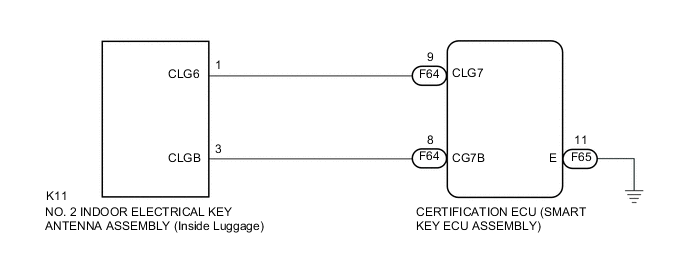
The certification ECU (smart key ECU assembly) generates a request signal and transmits the signal to the No. 2 indoor electrical key antenna assembly (inside luggage). For the No. 2 indoor electrical key antenna assembly (inside luggage) to detect when the key is inside the luggage compartment, the signal from the certification ECU (smart key ECU assembly) requesting a response from the key is transmitted inside the luggage compartment. DTC B27A7 is stored by the certification ECU (smart key ECU assembly) when an open circuit is detected between the certification ECU (smart key ECU assembly) and No. 2 indoor electrical key antenna assembly (inside luggage) (between terminals CLG7 and CLG6, or terminals CG7B and CLGB).
| DTC No. | DTC Detection Condition | Trouble Area | DTC Output Confirmation Operation |
|---|---|---|---|
| B27A7 | An open circuit is detected in the circuit between the certification ECU (smart key ECU assembly) and No. 2 indoor electrical key antenna assembly (inside luggage) (CLG7 - CLG6, CG7B - CLGB) (1 trip detection logic*1). |
|
Any time*2 |
-
*1: Only output while a malfunction is present.
-
*2: Only when the vehicle is stopped.
| Vehicle Condition when Malfunction Detected | Fail-safe Operation when Malfunction Detected |
|---|---|
| When key is in luggage compartment:
|
- |
| DTC No. | Data List and Active Test |
|---|---|
| B27A7 | Key diagnostic mode can be used to perform troubleshooting |
WIRING DIAGRAM
CAUTION / NOTICE / HINT
Note
-
The entry and start system (for entry function) uses a multiplex communication system (LIN communication system) and the CAN communication system. Inspect the communication function by following How to Proceed with Troubleshooting Click here. Troubleshoot the entry and start system (for entry function) after confirming that the communication systems are functioning properly.
-
When using the intelligent tester with the engine switch off to troubleshoot: Connect the intelligent tester to the DLC3 and turn a courtesy light switch on and off at 1.5-second intervals until communication between the intelligent tester and vehicle begins.
-
Before replacing the certification ECU (smart key ECU assembly), refer to the entry and start system (for entry function) Click here.
-
No. 2 indoor electrical key antenna assembly (inside luggage) has an antenna coil between CLG6 and CLGB terminals.
PROCEDURE
-
CHECK CONNECTOR CONNECTION CONDITION
-
Turn the engine switch off.
-
Check that the connectors are properly connected to the certification ECU (smart key ECU assembly) and the No. 2 indoor electrical key antenna assembly (inside luggage).
OK Connectors are properly connected.
NG 
CONNECT CONNECTORS PROPERLY
OK 
-
-
CHECK HARNESS AND CONNECTOR (NO. 2 INDOOR ELECTRICAL KEY ANTENNA - CERTIFICATION ECU)
-
Disconnect the F64 certification ECU (smart key ECU assembly) connector.
-
Disconnect the K11 No. 2 indoor electrical key antenna assembly (inside luggage) connector.
-
Measure the resistance according to the value(s) in the table below.
Standard Resistance (Check for Open) Tester Connection Condition Specified Condition F64-9 (CLG7) - K11-1 (CLG6) Always Below 1 Ω F64-8 (CG7B) - K11-3 (CLGB) Always Below 1 Ω Standard Resistance (Check for Short) Tester Connection Condition Specified Condition F64-9 (CLG7) - Body ground Always 10 kΩ or higher K11-1 (CLG6) - Body ground Always 10 kΩ or higher F64-8 (CG7B) - Body ground Always 10 kΩ or higher K11-3 (CLGB) - Body ground Always 10 kΩ or higher
NG
REPAIR OR REPLACE HARNESS OR CONNECTOR
OK
-
-
CHECK CERTIFICATION ECU (SMART KEY ECU ASSEMBLY) (OUTPUT TO NO. 2 INDOOR ELECTRICAL KEY ANTENNA)
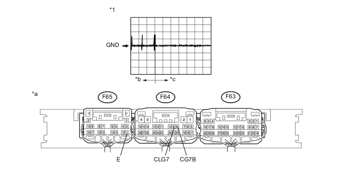
Text in Illustration *1 Waveform - - *a Component with harness connected
(Certification ECU (smart key ECU assembly))
*b Door open *c After approximately 30 seconds from when the door is closed - -
-
Reconnect the F64 certification ECU (smart key ECU assembly) connector.
-
Reconnect the K11 No. 2 indoor electrical key antenna assembly (inside luggage) connector.
-
Using an oscilloscope, check the waveform.
Tech Tips
Check that the customizing "Ignition Available Area" setting of entry and start system is All Click here.
OK Tester Connection Switch Condition Tool Setting Specified Condition F64-9 (CLG7) - F65-11 (E) Procedure:
-
Engine switch off
-
Door is open
-
Door is closed
-
30 seconds elapse
-
Electrical key transmitter not inside vehicle
-
Electrical key transmitter brought outside detection area
2 V/DIV., 500 ms/DIV. Pulse generation (See waveform) F64-8 (CG7B) - F65-11 (E) Procedure:
-
Engine switch off
-
Door is open
-
Door is closed
-
30 seconds elapse
-
Electrical key transmitter not inside vehicle
-
Electrical key transmitter brought outside detection area
2 V/DIV., 500 ms/DIV. Pulse generation (See waveform) -
NG
REPLACE CERTIFICATION ECU (SMART KEY ECU ASSEMBLY)
OK
-
-
REPLACE NO. 2 INDOOR ELECTRICAL KEY ANTENNA ASSEMBLY (Inside Luggage)
-
Temporarily replace the No. 2 indoor electrical key antenna assembly (inside luggage) with a new or normally functioning one Click here.
NEXT
-
-
CHECK DTC OUTPUT
-
Clear the DTCs Click here.
-
Recheck for DTCs Click here.
OK B27A7 output does not recur.
OK
END (NO. 2 INDOOR ELECTRICAL KEY ANTENNA ASSEMBLY WAS DEFECTIVE)
NG
REPLACE CERTIFICATION ECU (SMART KEY ECU ASSEMBLY)
-