KEY REMINDER WARNING SYSTEM(w/o Entry and Start System) TERMINALS OF ECU
-
CHECK MAIN BODY ECU (MULTIPLEX NETWORK BODY ECU), INSTRUMENT PANEL JUNCTION BLOCK ASSEMBLY
w/o Theft Deterrent System
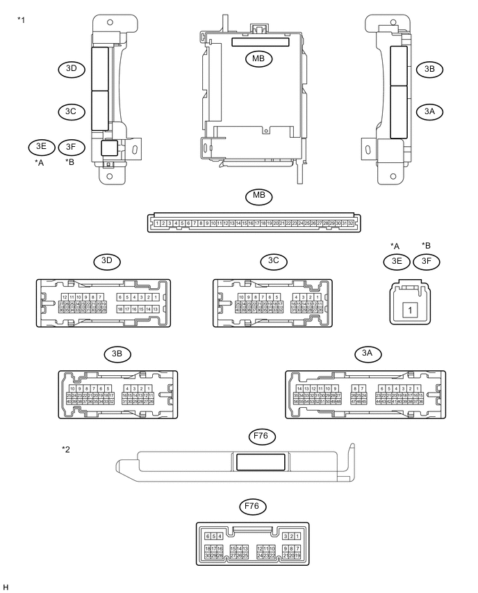
Text in Illustration *A For LHD *B For RHD *1 Instrument Panel Junction Block Assembly *2 Main Body ECU
(Multiplex Network Body ECU)
w/ Theft Deterrent System
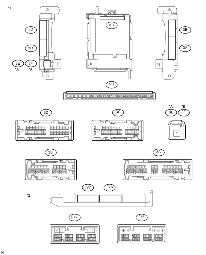
Text in Illustration *1 Instrument Panel Junction Block Assembly *2 Main Body ECU
(Multiplex Network Body ECU)
-
Remove the main body ECU (multiplex network body ECU) from the instrument panel junction block assembly.
-
Disconnect the F76 main body ECU (multiplex network body ECU) connector.
-
Measure the voltage and resistance according to the value(s) in the table below.
Terminal No. (Symbol) Wiring Color Terminal Description Condition Specified Condition MB-11 (GND1) - Body ground None - Body ground Ground Always Below 1 Ω MB-30 (BECU) - Body ground None - Body ground Battery power supply (for CPU) Always 11 to 14 V MB-29 (ACC) - Body ground None - Body ground ACC power supply Engine switch on (ACC) 11 to 14 V MB-32 (IG) - Body ground None - Body ground Engine switch power supply Engine switch on (IG) 11 to 14 V F76-17 (KSW) - Body ground Y - Body ground Unlock warning switch input No Key in ignition key cylinder (off) 10 kΩ or higher Key inserted ignition key cylinder (on) Below 1 Ω Tech Tips
If the result is not as specified, there may be a malfunction in the wire harness.
-
Install the main body ECU (multiplex network body ECU) to the instrument panel junction block assembly.
-
Reconnect the F76 main body ECU (multiplex network body ECU) connector.
-
Measure the voltage according to the value(s) in the table below.
Terminal No. (Symbol) Wiring Color Terminal Description Condition Specified Condition 3D-36 - Body ground L - Body ground Front door LH courtesy light switch input Front door LH open Below 1 V Front door LH closed Pulse generation*1 11 to 14 V*2 F76-19 (FRCY) - Body ground Y - Body ground Front door RH courtesy light switch input Front door RH open Below 1 V Front door RH closed Pulse generation*1 11 to 14 V*2 F76-17 (KSW) - Body ground Y - Body ground Unlock warning switch input No Key in ignition key cylinder (off) 11 to 14 V Key inserted ignition key cylinder (on) Below 1 V
-
*1: w/ Rear Fog Light
-
*2: w/o Rear Fog Light
If the result is not as specified, the main body ECU (multiplex network body ECU) may have a malfunction.
-
-