WIRELESS DOOR LOCK CONTROL SYSTEM(w/ Entry and Start System), Diagnostic DTC:B1242
| DTC Code | DTC Name |
|---|---|
| B1242 | Wireless Door Lock Tuner Circuit Malfunction |
DESCRIPTION
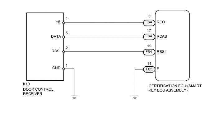
The door control receiver is used to receive electrical waves relating to the entry functions of the entry and start system. The certification ECU (smart key ECU assembly) decodes the requested entry and start system operation by identifying a key code based on the electric waves received via the door control receiver. The door control receiver receives a signal from the door control transmitter and sends signals to the main body ECU (multiplex network body ECU) through the certification ECU (smart key ECU assembly). The certification ECU (smart key ECU assembly) then sends a command, according to the requested operation, to each ECU (ex. if door lock operation is requested, the certification ECU (smart key ECU assembly) sends a door lock command to the main body ECU (multiplex network body ECU)).
| DTC No. | DTC Detection Condition | Trouble Area |
|---|---|---|
| B1242 |
|
|
WIRING DIAGRAM
CAUTION / NOTICE / HINT
Note
-
When replacing or inspecting the door control receiver and wire harness, do not change the position or length of the wire harness. If the wire harness is too close to the door control receiver, entry and wireless function performance may be affected.
-
Before performing the inspection, check that there are no problems related to the CAN communication system.
PROCEDURE
-
INSPECT CERTIFICATION ECU (SMART KEY ECU ASSEMBLY)
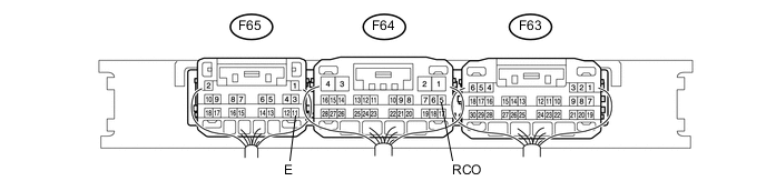
Text in illustration *1 Component with harness connected
(certification ECU (smart key ECU assembly))
- -
-
Measure the voltage according to the value(s) in the table below.
Standard Resistance Tester Connection Condition Specified Condition F65-11 (E) - Body ground Always Below 1 Ω Standard Voltage Tester Connection Condition Specified Condition F64-5 (RC0) - F65-11 (E) Engine switch off and transmitter switch pressed Below 1 V→ 4.5 to 5.5 V F64-19 (RSSI) - F65-11 (E) Engine switch off, all doors closed, all doors locked and transmitter switch pressed 11 to 14 V → Below 2 V F64-17 (RDAS) - F65-11 (E) Engine switch off, all doors closed, all doors locked and transmitter switch pressed Below 2 V → 11 to 14 V → Below 2 V
NG 
REPLACE DOOR CONTROL RECEIVER Click here
OK 
-
-
CHECK HARNESS AND CONNECTOR (DOOR CONTROL RECEIVER - CERTIFICATION ECU)
-
Disconnect the F64 certification ECU (smart key ECU assembly) connector.
-
Disconnect the K10 door control receiver connector.
-
Measure the resistance according to the value(s) in the table below.
Standard Resistance Tester Connection Condition Specified Condition F64-19 (RSSI) - K10-2 (RSSI) Always Below 1 Ω F64-17 (RDAS) - K10-5 (DATA) Always Below 1 Ω F64-5 (RCO) - K10-4 (+5) Always Below 1 Ω
OK
REPLACE CERTIFICATION ECU (SMART KEY ECU ASSEMBLY)
NG
REPAIR OR REPLACE HARNESS OR CONNECTOR
-