POWER DOOR LOCK CONTROL SYSTEM TERMINALS OF ECU
-
CHECK MAIN BODY ECU (MULTIPLEX NETWORK BODY ECU), INSTRUMENT PANEL JUNCTION BLOCK ASSEMBLY
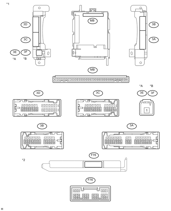
w/o Theft Deterrent System
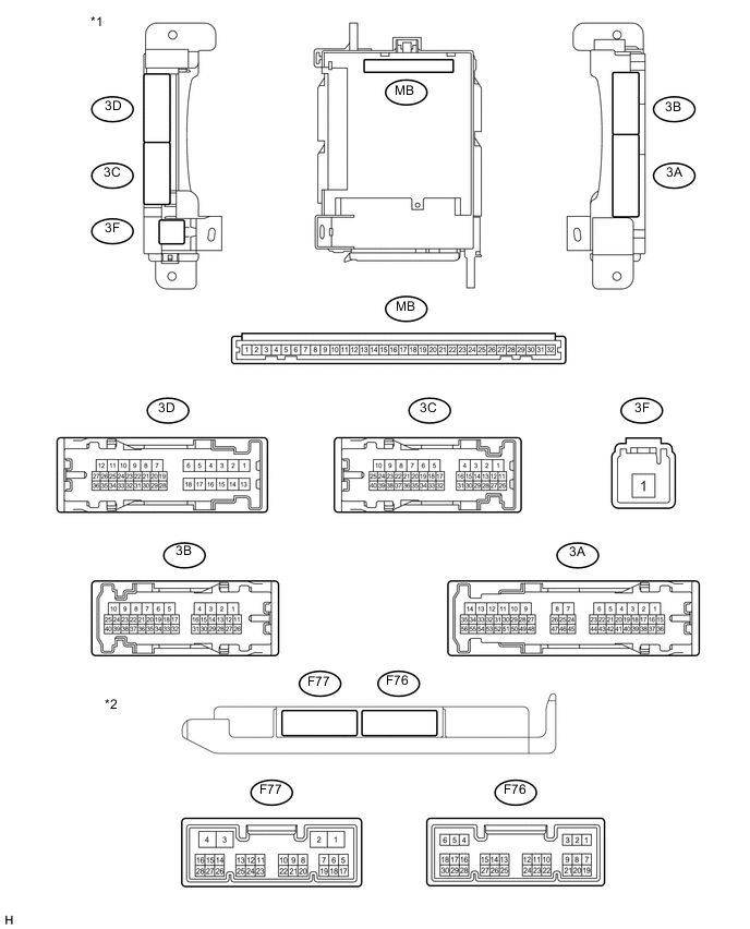
Text in Illustration *A for LHD *B for RHD *1 Instrument Panel Junction Block Assembly *2 Main Body ECU (Multiplex Network Body ECU) w/ Theft Deterrent System
Text in Illustration *1 Instrument Panel Junction Block Assembly *2 Main Body ECU (Multiplex Network Body ECU)
-
Remove the main body ECU (multiplex network body ECU) from the instrument panel junction block assembly.
-
Measure the resistance and voltage between each terminal of the wire harness side connectors and body ground.
Terminal No. (Symbol) Wiring Color Terminal Description Condition Specified Condition MB-11 (GND1) - Body ground None - Body ground Ground Always Below 1 Ω MB-30 (BECU) - Body ground None - Body ground Battery power supply (for CPU) Always 11 to 14 V MB-31 (ALTB) - Body ground None - Body ground +B (power system alternator system) power supply Always 11 to 14 V MB-32 (IG) - Body ground None - Body ground Ignition power supply (IG signal) Ignition switch ON 11 to 14 V Ignition switch OFF Below 1 V Tech Tips
If the result is not as specified, there may be a malfunction on the wire harness side.
-
Install the main body ECU (multiplex network body ECU) to the instrument panel junction block assembly.
Terminal No. (Symbol) Wiring Color Terminal Description Condition Specified Condition 3D-36 - Body ground L - Body ground Front door LH courtesy light switch input Front door LH open Below 1 V Front door LH closed Pulse generation F76-19 (FRCY) - Body ground Y - Body ground Front door RH courtesy light switch input Front door RH open Below 1 V Front door RH closed Pulse generation F76-6 (LRCY) - Body ground*1 G - Body ground Rear door LH courtesy light switch input Rear door LH open Below 1 V Rear door LH closed Pulse generation Rear door RH courtesy light switch input Rear door RH open Below 1 V Rear door RH closed Pulse generation F76-6 (RCTY) - Body ground*2 V - Body ground Rear door RH courtesy light switch input Rear door RH open Below 1 V Rear door RH closed Pulse generation F76-24 (LCTY) - Body ground*2 V - Body ground Rear door LH courtesy light switch input Rear door LH open Below 1 V Rear door LH closed Pulse generation 3D-35 - Body ground B - Body ground Back door courtesy light switch input Back door open Below 1 V Back door closed Pulse generation*1 11 to 14 V*2 F76-17 (KSW) - Body ground*3 Y - Body ground Unlock warning switch input NO key in ignition key cylinder (off) 10 kΩ or higher Key inserted (on) Below 1 Ω F76-11 (L2) - Body ground B - Body ground Driver side door key-linked lock input Driver side door key cylinder in lock position Below 1 V Driver side door key cylinder in neutral position Pulse generation F76-12 (UL2) - Body ground G - Body ground Driver side door key-linked unlock input Driver side door key cylinder in unlock position Below 1 V Driver side door key cylinder in neutral position Pulse generation 3B-2 - Body ground V - Body ground Door lock motor lock drive output (for front RH side) Driver side door control switch not pushed and driver side door key cylinder in neutral position Below 1 V Lock side of driver side door control switch pushed or driver side door key cylinder in lock position 11 to 14 V 3B-1 - Body ground Y - Body ground Door lock motor lock drive output (for front LH side) Driver side door control switch not pushed and driver side door key cylinder in neutral position Below 1 V Lock side of driver side door control switch pushed or driver side door key cylinder in lock position 11 to 14 V 3D-12 - Body ground L - Body ground Door lock motor lock drive output (for rear RH side) Driver side door control switch not pushed and driver side door key cylinder in neutral position Below 1 V Lock side of driver side door control switch pushed or driver side door key cylinder in lock position 11 to 14 V 3D-11 - Body ground GR - Body ground Door lock motor lock drive output (for rear LH side) Driver side door control switch not pushed and driver side door key cylinder in neutral position Below 1 V Lock side of driver side door control switch pushed or driver side door key cylinder in lock position 11 to 14 V 3D-9 - Body ground Y - Body ground Door lock motor lock drive output (for back door) Back door closed 11 to 14 V Back door opener - switch pushed Below 1 V 3B-3 - Body ground R - Body ground Door lock motor unlock drive output (for front RH side) Driver side door control switch not pushed and driver side door key cylinder in neutral position Below 1 V Unlock side of - driver side door control switch pushed or driver side door key cylinder in unlock position 11 to 14 V 3B-4 - Body ground L - Body ground Door lock motor unlock drive output (for front LH side) Driver side door control switch not pushed and driver side door key cylinder in neutral position Below 1 V Unlock side of - driver side door control switch pushed or driver side door key cylinder in unlock position 11 to 14 V 3D-8 - Body ground P - Body ground Door lock motor unlock drive output (for rear RH side) Driver side door control switch not pushed and driver side door key cylinder in neutral position Below 1 V Unlock side of - driver side door control switch pushed or driver side door key cylinder in unlock position 11 to 14 V 3D-7 - Body ground LG - Body ground Door lock motor unlock drive output (for rear LH side) Driver side door control switch not pushed and driver side door key cylinder in neutral position Below 1 V Unlock side of - driver side door control switch pushed or driver side door key cylinder in unlock position 11 to 14 V F76-18 (LSFR) - Body ground LG - Body ground Front door RH lock position switch input Front door RH unlocked Below 1 V Front door RH locked Pulse generation F76-7 (LSFL) - Body ground*1, *4 L - Body ground Front door LH lock position switch input Front door LH unlocked Below 1 V Front door LH locked Pulse generation 3D-25 - Body ground*1, *4 V - Body ground Rear door RH lock position switch input Rear door RH unlocked Below 1 V Rear door RH locked Pulse generation 3D-24 - Body ground*1, *4 Y - Body ground Rear door LH lock position switch input Rear door LH unlocked Below 1 V Rear door LH locked Pulse generation
-
*1: w/ Rear Fog Light
-
*2: w/o Rear Fog Light
-
*3: w/o Entry and Start System
-
*4: w/o Rear Fog Light and w/ Entry and Start System
-
-
-
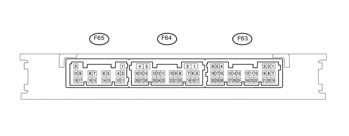
CHECK CERTIFICATION ECU (w/ Entry and Start System)
-
Disconnect the F65 certification ECU (smart key ECU assembly) connectors.
-
Measure the voltage and resistance according to the value(s) in the table below.
Terminal No. (Symbol) Wiring Color Terminal Description Condition Specified Condition F65-2 (+B) - F65- 11 (E) W - BR +B power supply Always 11 to 14 V F65-10 (CUTB) - F65-11 (E) Y - BR Dark current cut pin* Always 11 to 14 V *: In order to prevent the battery from being depleted when the vehicle is shipped long distances, a fuse that cuts unnecessary electrical load while the vehicle is being shipped is set in the circuit. If the fuse is removed, the circuit becomes open. If the fuse that is between the battery and terminal CUTB is removed and the circuit is open, the certification ECU (smart key ECU assembly) changes to a certain control mode (example: the transmission of electric waves every 250 ms. that form the detection area stops).
If the result is not as specified, there may be a malfunction on the wire harness side or the fuse is removed.
-
Reconnect the F65 certification ECU (smart key ECU assembly) connector.
-
Measure the voltage according to the value(s) in the table below.
Terminal No. (Symbol) Wiring Color Terminal Description Condition Specified Condition F64-27 (TSW5) - Body ground L - Body ground Back door unlock switch signal input Back door opener switch assembly (open switch) off → on Pulse generation → Below 1 V F64-28 (TSW6) - Body ground W - Body ground Back door lock switch signal input Back door opener switch assembly (lock switch) off → on Pulse generation → Below 1 V
-
-
CHECK DOUBLE LOCK DOOR CONTROL RELAY (w/ Double Locking System)

-
Disconnect the F79 double lock door control relay connector.
-
Measure the voltage according to the value(s) in the table below.
Terminal No. (Symbol) Wiring Color Terminal Description Condition Specified Condition F79-1 (+B) - F79-14 (GND) L - W-B Battery power supply Always 11 to 14 V F79-7 (CPUB) - F79-14 (GND) BE - W-B ECU power supply Always 11 to 14 V F79-14 (GND) - Body ground W-B - Body ground Ground Always Below 1 V If the result is not as specified, there may be a malfunction on the wire harness side.
-
Reconnect the F79 double lock door control relay connector.
-
Measure the voltage and resistance according to the value(s) in the table below.
Terminal No. (Symbol) Wiring Color Terminal Description Condition Specified Condition F79-4 (ACTR) - F79-14 (GND) W - W-B All door double lock motor set off output Door lock set → unset Below 1 V → 11 to 14 V → Below 1 V F79-3 (ACTS) - F79-14 (GND) B - W-B All door double lock motor set on output Door lock unset → set Below 1 V → 11 to 14 V → Below 1 V F79-5 (DLPD) - F79-14 (GND) P - W-B Double lock position switch signal Double lock set Below 1 Ω F79-5 (DLPD) - F79-14 (GND) P - W-B Double lock position switch signal Double lock unset 10 kΩ or higher F79-6 (DLPP) - F79-14 (GND) GR - W-B Double lock position switch signal Double lock set Below 1 Ω F79-6 (DLPP) - F79-14 (GND) GR - W-B Double lock position switch signal Double lock unset 10 kΩ or higher If the result is not as specified, the ECU may have a malfunction.
-