WIRELESS DOOR LOCK CONTROL SYSTEM(w/o Entry and Start System) TERMINALS OF ECU
-
CHECK MAIN BODY ECU (MULTIPLEX NETWORK BODY ECU), INSTRUMENT PANEL JUNCTION BLOCK ASSEMBLY
w/o Theft Deterrent System
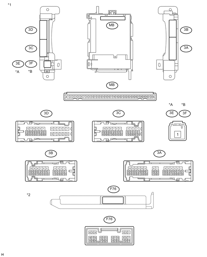
Text in Illustration *A for LHD *B for RHD *1 Instrument Panel Junction Block Assembly *2 Main Body ECU (Multiplex Network Body ECU) w/ Theft Deterrent System
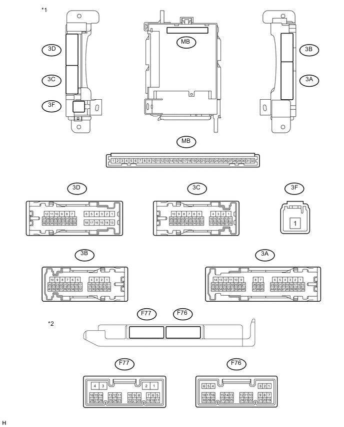
Text in Illustration *1 Instrument Panel Junction Block Assembly *2 Main Body ECU (Multiplex Network Body ECU)
-
Remove the main body ECU (multiplex network body ECU) from the instrument panel junction block assembly.
-
Measure the resistance and voltage between each terminal of the wire harness side connectors and body ground.
Terminal No. (Symbol) Wiring Color Terminal Description Condition Specified Condition MB-11 (GND1) - Body ground None - Body ground Ground Always Below 1 Ω MB-30 (BECU) - Body ground None - Body ground Battery power supply (for CPU) Always 11 to 14 V MB-32 (IG) - Body ground None - Body ground Ignition power supply (IG signal) Ignition switch ON 11 to 14 V Ignition switch OFF Below 1 V Tech Tips
If the result is not as specified, there may be a malfunction on the wire harness side.
-
Install the main body ECU (multiplex network body ECU) to the instrument panel junction block assembly.
Terminal No. (Symbol) Wiring Color Terminal Description Condition Specified Condition 3D-36 - Body ground L - Body ground Front door LH courtesy light switch input Front door LH open Below 1 V Front door LH closed Pulse generation F76-19 (FRCY) - Body ground Y - Body ground Front door RH courtesy light switch input Front door RH open Below 1 V Front door RH closed Pulse generation F76-6 (LRCY) - Body ground*1 G - Body ground Rear door courtesy light switch input Rear door open Below 1 V Rear door closed Pulse generation F76-6 (RCTY) - Body ground*2 V - Body ground Rear door RH courtesy light switch input Rear door RH open Below 1 V Rear door RH closed Pulse generation F76-24 (LCTY) - Body ground*2 V - Body ground Rear door LH courtesy light switch input Rear door LH open Below 1 V Rear door LH closed Pulse generation 3D-35 - Body ground B - Body ground Back door courtesy light switch input Back door open Below 1 V Back door closed Pulse generation*1 11 to 14 V*2 F76-17 (KSW) - Body ground Y - Body ground Unlock warning switch input NO key in ignition key cylinder (off) 10 kΩ or higher Key inserted (on) Below 1 Ω F76-11 (L2) - Body ground B - Body ground Driver side door key-linked lock input Driver side door key cylinder in lock position Below 1 V Driver side door key cylinder in neutral position Pulse generation F76-12 (UL2) - Body ground G - Body ground Driver side door key-linked unlock input Driver side door key cylinder in unlock position Below 1 V Driver side door key cylinder in neutral position Pulse generation 3B-2 - Body ground V - Body ground Door lock motor lock drive output (for front RH side) Driver side door control switch not pushed and driver side door key cylinder in neutral position Below 1 V Lock side of driver side door control switch pushed or driver side door key cylinder in lock position 11 to 14 V 3B-1 - Body ground Y - Body ground Door lock motor lock drive output (for front LH side) Driver side door control switch not pushed and driver side door key cylinder in neutral position Below 1 V Lock side of driver side door control switch pushed or driver side door key cylinder in lock position 11 to 14 V 3B-12 - Body ground L - Body ground Door lock motor lock drive output (for rear RH side) Driver side door control switch not pushed and driver side door key cylinder in neutral position Below 1 V Lock side of driver side door control switch pushed or driver side door key cylinder in lock position 11 to 14 V 3D-11 - Body ground GR - Body ground Door lock motor lock drive output (for rear LH side) Driver side door control switch not pushed and driver side door key cylinder in neutral position Below 1 V Lock side of driver side door control switch pushed or driver side door key cylinder in lock position 11 to 14 V 3D-9 - Body ground Y - Body ground Door lock motor lock drive output (for back door) Back door closed 11 to 14 V Back door opener switch pushed Below 1 V 3B-3 - Body ground R - Body ground Door lock motor unlock drive output (for front RH side) Driver side door control switch not pushed and driver side door key cylinder in neutral position Below 1 V Unlock side of driver side door control switch pushed or driver side door key cylinder in unlock position 11 to 14 V 3B-4 - Body ground L - Body ground Door lock motor unlock drive output (for front LH side) Driver side door control switch not pushed and driver side door key cylinder in neutral position Below 1 V Unlock side of driver side door control switch pushed or driver side door key cylinder in unlock position 11 to 14 V 3D-8 - Body ground P - Body ground Door lock motor unlock drive output (for rear RH side) Driver side door control switch not pushed and driver side door key cylinder in neutral position Below 1 V Unlock side of driver side door control switch pushed or driver side door key cylinder in unlock position 11 to 14 V 3D-7 - Body ground LG - Body ground Door lock motor unlock drive output (for rear LH side) Driver side door control switch not pushed and driver side door key cylinder in neutral position Below 1 V Unlock side of driver side door control switch pushed or driver side door key cylinder in unlock position 11 to 14 V F76-18 (LSFR) - Body ground LG - Body ground Front door RH lock position switch input Front door RH unlocked Below 1 V Front door RH locked Pulse generation
-
*1: w/ Rear Fog Light
-
*2: w/o Rear Fog Light
-
-