GENERATOR REASSEMBLY

PROCEDURE
-
INSTALL GENERATOR DRIVE END FRAME BEARING
-
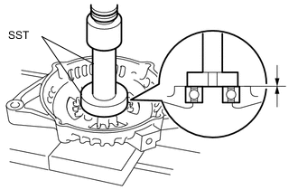
Using SST and a press, press in a new generator drive end frame bearing.
- SST
- 09950-60010 ( 09951-00470 )
- 09950-70010 ( 09951-07100 )
-
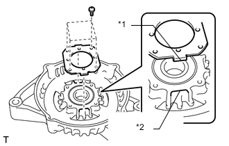
Text in Illustration *1 Tab *2 Cutout Fit the tabs of the bearing retainer into the cutouts on the generator drive end frame assembly to install the bearing retainer.
-
Install the 4 screws.
- Torque:
- 2.3 N*m { 23 kgf*cm, 20 in.*lbf }
-
-
INSTALL GENERATOR ROTOR ASSEMBLY
-
Place the generator drive end frame assembly on the generator pulley.
-
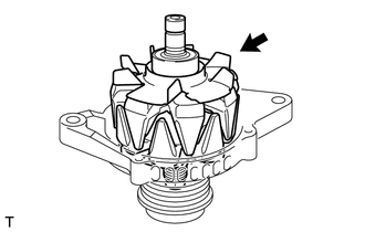
Install the generator rotor assembly to the generator drive end frame assembly.
-
-
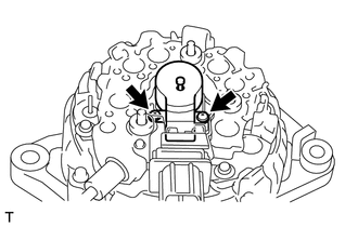
INSTALL GENERATOR COIL ASSEMBLY
-
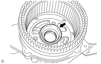
Install a new bearing cover packing on the generator coil assembly.
-
Using SST and a press, slowly press in the generator coil assembly.
- SST
- 09612-70100 ( 09612-07240 )
-
Install the 4 bolts.
- Torque:
- 5.9 N*m { 60 kgf*cm, 52 in.*lbf }
-
-
INSTALL GENERATOR BRUSH HOLDER ASSEMBLY
-
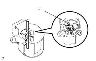
Text in Illustration *1 Pin (1.0 mm) diameter While pushing the 2 brushes into the generator brush holder assembly, insert a 1.0 mm (0.0394 in.) diameter pin into the brush holder hole.
-
Install the generator brush holder assembly to the generator coil assembly with the 2 screws.
- Torque:
- 1.8 N*m { 18 kgf*cm, 16 in.*lbf }
-
Text in Illustration *1 Pin (1.0 mm) diameter Pull out the pin from the generator brush holder assembly.
-
-
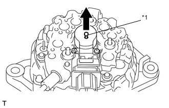
INSTALL GENERATOR TERMINAL INSULATOR
-
Install the generator terminal insulator to the generator coil assembly.
Note
Be sure to install the terminal insulator as shown in the illustration.
-
-
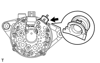
INSTALL CLAMP
-
Install the clamp with the bolt.
- Torque:
- 4.6 N*m { 47 kgf*cm, 41 in.*lbf }
-
-
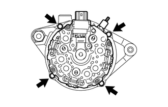
INSTALL GENERATOR REAR END COVER
-
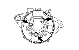
Install the generator rear end cover to the generator coil assembly with the 3 bolts.
- Torque:
- 4.6 N*m { 47 kgf*cm, 41 in.*lbf }
-
-
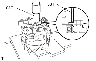
INSTALL GENERATOR PULLEY
-
Temporarily install the generator clutch pulley onto the rotor shaft.
-
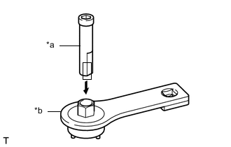
Text in Illustration *a SST (A) *b SST (B) Confirm SST (A) and (B) shown in the illustration.
- SST
- 09820-63021
-
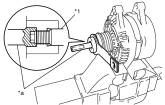
Text in Illustration *1 Rotor Shaft *a SST (A) Place the rotor shaft end into SST (A).
-
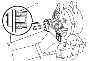
Text in Illustration *1 Clutch Pulley *a SST (B) Fit SST (B) to the generator clutch pulley.
-
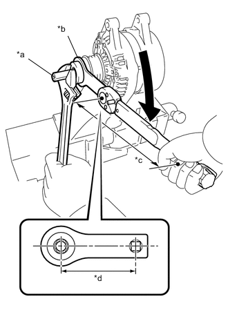
Text in Illustration *a SST (A) *b SST (B) *c Fulcrum Length 318 mm *d Fulcrum Length 100 mm Tighten the pulley by turning SST (B) in the direction shown in the illustration.
- Torque:
- without SST
- 80 N*m { 816 kgf*cm, 59 ft.*lbf }
- with SST
- 61 N*m { 622 kgf*cm, 45 ft.*lbf }
Note
-
Use a torque wrench with a fulcrum length of 318 mm (1.043 ft.).
-
This torque value is effective when SST is parallel to the torque wrench.
-
Check that the drive end frame is secured in the vise tightly.
-
Hold SST (A) tightly during the operation.
-
Remove the generator assembly from SST.
-
Check that the clutch pulley rotates smoothly.
-
-
INSTALL GENERATOR PULLEY CAP
-
Install a new clutch pulley cap to the clutch pulley.
-