CHARGING SYSTEM TERMINALS OF ECU
-
CHECK ECM
Tech Tips
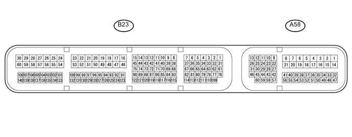
The standard normal voltage between each pair of ECM terminals is shown in the table below. The appropriate conditions for checking each pair of terminals are also indicated. The result of checks should be compared with the standard normal voltage for that pair of terminals, displayed in the Specified Condition column. The illustration above can be used as a reference to identify the ECM terminal locations.
Terminal No. (Symbol) Wiring Color Terminal Description Condition Specified Condition A58-45 (RLO) - B23-16 (E1) W - W-B Generator After engine warmed up, during charging control, vehicle accelerated or driven at constant speed Pulse generation (see waveform 1) After engine warmed up, during charging control, vehicle decelerated Pulse generation (see waveform 2) A58-34 (VCIB) - A58-36 (EIB) P - V Power source of battery current sensor assembly Ignition switch ON 4.5 to 5.5 V B23-86 (THB) - A58-36 (EIB) G - V Battery temperature sensor Ignition switch ON 0.2 to 4.8 V A58-35 (IB) - A58-36 (EIB) L - V Battery current sensor Ignition switch ON 0.2 to 4.8 V B23-16 (E1) - Body ground W-B - Body ground Ground Always Below 1 Ω A58-1 (BATT) - B23-16 (E1) Y - W-B Battery (for measuring battery voltage and for ECM memory) Always 11 to 14 V *: The ECM terminal voltage is constant regardless of the output voltage from the sensor.
-
Using an oscilloscope, check the signal waveform of the ECU.
Tech Tips
The oscilloscope waveform shown in the illustration is an example for reference only. Waveforms with noise or chattering are not shown.
-
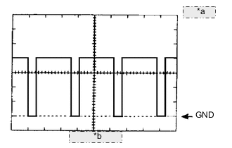
*a 2 V/DIV. *b 50 msec./DIV. Waveform 2
Tester Connection Tool Setting Vehicle Condition Specified Condition A58-45 (RLO) - B23-16 (E1) 2 V/DIV., 50 msec./DIV. After engine warmed up, during charging control, vehicle accelerated or driven at constant speed Correct waveform as shown in illustration Tech Tips
As the duty cycle changes in accordance with the electrical load and battery condition, the output waveform also changes.
-
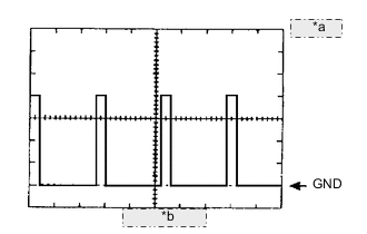
*a 2 V/DIV. *b 50 msec./DIV. Waveform 3
Tester Connection Tool Setting Vehicle Condition Specified Condition A58-45 (RLO) - B23-16 (E1) 2 V/DIV., 50 msec./DIV. After engine warmed up, during charging control, vehicle decelerated Correct waveform as shown in illustration Tech Tips
As the duty cycle changes in accordance with the electrical load and battery condition, the output waveform also changes.
-
-