GENERATOR(for 80A Type) INSPECTION

PROCEDURE
-
INSPECT GENERATOR CLUTCH PULLEY
-
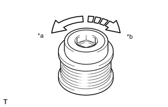
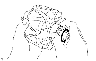
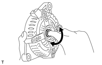
Text in Illustration *a Free *b Lock Hold the center of the generator clutch pulley, and confirm that the outer ring turns counterclockwise and does not turn clockwise.
If the result is not as specified, replace the generator clutch pulley.
-
-
INSPECT GENERATOR BRUSH HOLDER ASSEMBLY
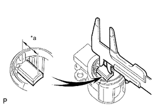
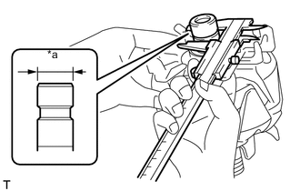
Text in Illustration *a Length
-
Using a vernier caliper, measure the length of the exposed brushes.
Standard exposed length 9.5 to 11.5 mm (0.374 to 0.453 in.) Minimum exposed length 4.5 mm (0.177 in.) If the exposed length is less than the minimum, replace the generator brush holder assembly.
-
-
INSPECT GENERATOR ROTOR ASSEMBLY
-
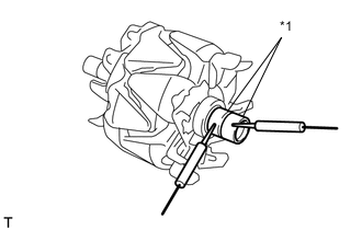
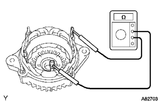
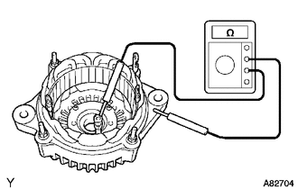
Check the generator rotor for open circuits.
-
Measure the resistance according to the value(s) in the table below.
Standard Resistance Tester Connection Condition Specified Condition Slip ring - Slip ring 20°C (68°F) 1.7 to 2.1 Ω Text in Illustration *1 Slip Ring If the resistance is not as specified, replace the generator rotor assembly.
-
-
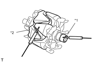
Text in Illustration *1 Slip Ring *2 Rotor Check the generator rotor for short circuits.
-
Measure the resistance according to the value(s) in the table below.
Standard Resistance Tester Connection Condition Specified Condition Slip ring - Rotor Always 10 MΩ or higher If the result is not as specified, replace the generator rotor assembly.
-
-
Check that the generator rotor bearing is not rough or worn.
If necessary, replace the generator rotor assembly.
-
Text in Illustration *a Diameter Using a vernier caliper, measure the slip ring diameter.
Standard diameter 14.2 to 14.4 mm (0.559 to 0.567 in.) Minimum diameter 14.0 mm (0.551 in.) If the diameter is less than the minimum, replace the generator rotor assembly.
-
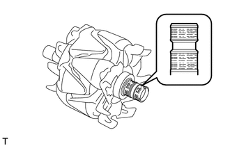
Check that the slip rings are not rough or scored.
If rough or scored, replace the generator rotor assembly.
-
-
INSPECT GENERATOR DRIVE END FRAME ASSEMBLY
-
Inspect the stator coil for open circuits.
-
Measure the resistance according to the value(s) in the table below.
Standard Resistance Tester Connection Condition Specified Condition Coil lead - Coil lead Always Below 1 Ω If the result is not as specified, replace the generator assembly.
-
-
Inspect the stator coil for ground.
-
Measure the resistance according to the value(s) in the table below.
Standard Resistance Tester Connection Condition Specified Condition Coil lead - Generator drive end frame assembly Always 10 kΩ or higher If the result is not as specified, replace the generator assembly.
-
-
Inspect the generator drive end frame bearing.
-
Check that the bearing is not rough or worn.
If necessary, replace the generator assembly.
-
-
-
INSPECT GENERATOR HOLDER WITH RECTIFIER
-
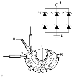
Check the resistance.
-
Measure the resistance according to the value(s) in the table below.
Standard Resistance Tester Connection Condition Specified Condition P1, P2, P3 and B Always Resistance of below 1 Ω in one direction but 10 kΩ or higher in the other direction. P1, P2, P3 and E Always Resistance of below 1 Ω in one direction but 10 kΩ or higher in the other direction. If the result is not as specified, replace the generator holder with rectifier.
-
-
-
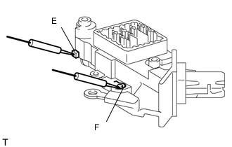
INSPECT GENERATOR REGULATOR ASSEMBLY
-
Check the resistance.
-
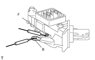
Measure the resistance according to the value(s) in the table below.
Standard Resistance Tester Connection Condition Specified Condition Terminals F - Terminals B Always When the positive and negative poles between terminals F and B are exchanged, there is a resistance of below 1 Ω in one direction but 10 kΩ or higher in the other direction. If the result is not as specified, replace the generator regulator assembly.
-
Measure the resistance according to the value(s) in the table below.
Standard Resistance Tester Connection Condition Specified Condition Terminals E - Terminals F Always When the positive and negative poles between terminals E and F are exchanged, there is a resistance of below 1 Ω in one direction but 10 kΩ or higher in the other direction. If the result is not as specified, replace the generator regulator assembly.
-
-