GENERATOR(for 80A Type) DISASSEMBLY

PROCEDURE
-
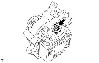
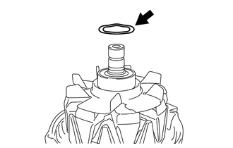
REMOVE GENERATOR PULLEY CAP
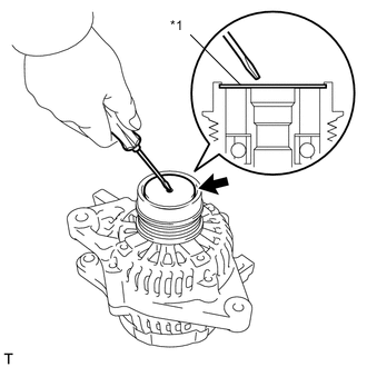
Text in Illustration *1 Generator Pulley Cap
-
Using a screwdriver, remove the generator pulley cap.
-
-
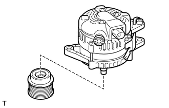
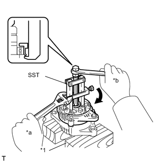
REMOVE GENERATOR CLUTCH PULLEY
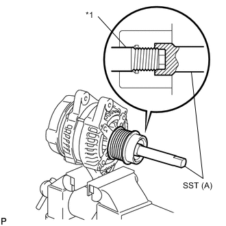
Text in Illustration *1 Rotor Shaft
-
Clamp the generator housing stay in a vise tightly.
-
Place the rotor shaft end into SST(A).
- SST
- 09820-63021
-
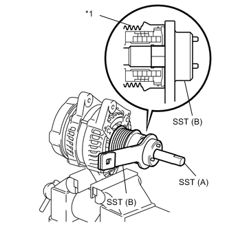
Text in Illustration *1 Generator Clutch Pulley Fit SST(B) onto the generator clutch pulley.
-
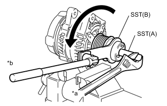
Text in Illustration *a Hold *b Turn Loosen the generator clutch pulley by turning SST(B) in the direction as shown in the illustration.
Note
-
Check that the generator housing stay is secured in a vise tightly.
-
Hold SST(A) tightly during the operation.
-
-
Remove SST from the generator assembly.
-
Remove the clutch pulley from the rotor shaft.
-
Remove the generator assembly from a vise.
-
-
REMOVE GENERATOR TERMINAL INSULATOR
-
Remove the nut and generator terminal insulator.
-
-
REMOVE GENERATOR REAR END COVER
-
Place the generator assembly on the generator clutch pulley.
-
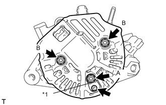
Text in Illustration *1 Rectifier Plate Remove the nut A, screw and rectifier plate.
-
Remove the 2 nuts B and the generator rear end cover.
-
-
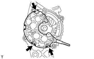
REMOVE GENERATOR BRUSH HOLDER ASSEMBLY
-
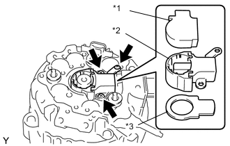
Text in Illustration *1 Generator Brush Cover *2 Generator Brush Holder Assembly *3 Generator Plate Seal Remove the generator brush cover from the generator brush holder assembly.
-
Remove the 3 screws and generator brush holder assembly.
-
Remove the generator plate seal.
-
-
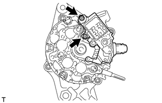
REMOVE GENERATOR REGULATOR ASSEMBLY
-
Remove the 2 screws and generator regulator assembly.
-
-
REMOVE GENERATOR HOLDER WITH RECTIFIER
-
Remove the 3 screws and generator holder with rectifier.
-
-
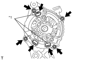
REMOVE GENERATOR ROTOR ASSEMBLY
-
Remove the 3 terminal insulators from the generator rectifier end frame.
Text in Illustration *1 Terminal Insulator -
Remove the 4 nuts.
-
Text in Illustration *1 Wooden Block *a Hold *b Turn Using SST, remove the generator rectifier end frame.
- SST
- 09286-46011
-
Remove the generator washer from the generator rotor assembly.
-
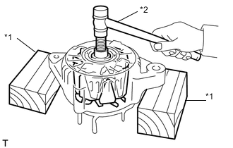
Text in Illustration *1 Wooden Block *2 Plastic Hammer Using a plastic hammer, remove the generator rotor assembly from the generator drive end frame assembly.
Note
Do not drop the generator rotor assembly.
Tech Tips
If the generator rotor assembly is engaged too firmly, gently tap the generator rotor shaft to remove it using a plastic hammer.
-