MAIN BODY ECU INSTALLATION
PROCEDURE
-
INSTALL MULTIPLEX NETWORK BODY ECU
Note
-
Prevent foreign matter from being mixed into the engagement, connector or terminal.
-
Do not touch the connector.
-

Text in illustration *a Housing Side Wall *b Guide *c 20° or more Contact the multiplex network body ECU guide against the housing side wall.
Tech Tips
The angle between the junction block and the main body ECU guide should be 20° or more.
-
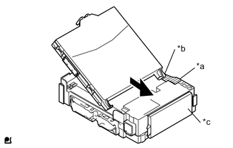
Text in illustration *a Hosing Side Wall *b Guide *c Fuse Area While aligning the guide with the housing side wall, slide the multiplex network body ECU toward the fuse area of the instrument panel junction block assembly.
-
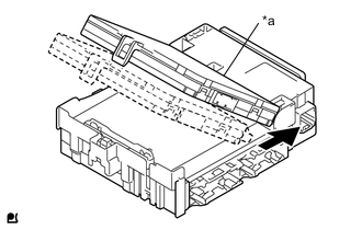
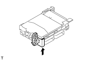
Text in illustration *a A surface Slide the multiplex network body ECU until it contacts the A surface.
Note
-
Slide the multiplex network body ECU gently.
-
Do not apply strong impact to the side of the multiplex network body ECU.
-
-
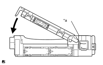
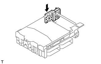
Text in illustration *a A surface Rotate the multiplex network body ECU while holding it against the instrument panel junction block assembly surface (axis of rotation).
-
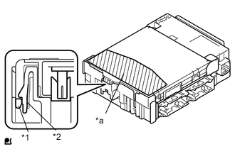
Text in illustration *1 Multiplex Network Body ECU *2 Instrument Panel Junction Block Assembly *a Push Area Rotate the multiplex network body ECU until it engages with the lock to install it.
Note
-
When pressing the multiplex network body ECU, press the push area as shown in the illustration.
-
A lock sound will be heard when the multiplex network body ECU is engaged.
-
Do not hit or weight the multiplex network body ECU when it engages with the instrument panel junction block assembly.
Tech Tips
If a lock sound is not heard, visually check the lock engagement. Check that the height of the multiplex network body ECU and instrument panel junction block assembly match.
-
-
-
INSTALL JUNCTION BLOCK BRACKET
-
Engage the claw and install the junction block bracket B.
-
-
INSTALL JUNCTION BLOCK BRACKET
-
Engage the claw and install the junction block bracket.
-
-
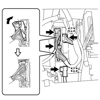
INSTALL INSTRUMENT PANEL JUNCTION BLOCK ASSEMBLY
-
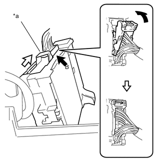
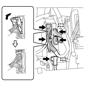
Connect the back side connector B indicated as shown in the illustration.
-
Slide the lever by the arrow indicated as shown in the illustration.
Text in illustration *a Lever -
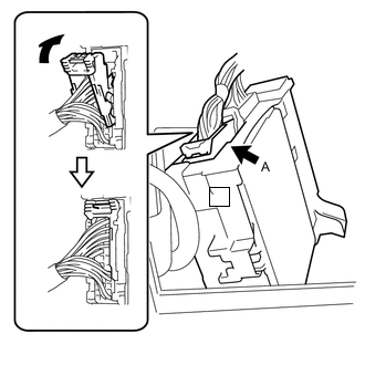
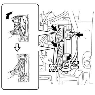
Connect the back side connector A indicated as shown in the illustration.
-
Engage the claw, 2 clamps and the connect the instrument panel junction block assembly.
-
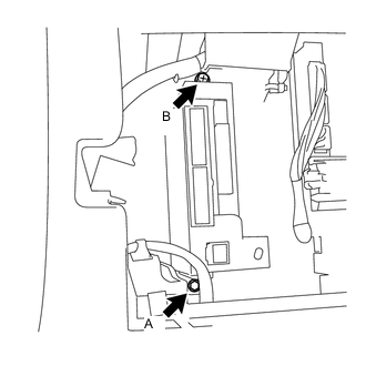
Install the instrument panel junction block assembly with the bolt A and the screw B.
- Torque:
- for Bolt A
- 8.4 N*m { 86 kgf*cm, 74 in.*lbf }
- Torque:
- for Screw B
- 8.4 N*m { 86 kgf*cm, 74 in.*lbf }
-
Connect each front side connector indicated as shown in illustration (for LHD).
-
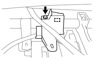
Install wire harness protector with the clamp and screw (for RHD).
-
Connect each front side connector indicated as shown in illustration (for RHD with Rear Fog Light).
-
Connect each front side connector indicated as shown in illustration (for RHD without Rear Fog Light).
-
-
INSTALL INSTRUMENT PANEL UNDER TRAY (for LHD)
-
INSTALL NO. 1 INSTRUMENT PANEL UNDER COVER SUB-ASSEMBLY (for LHD)
-
INSTALL NO. 2 INSTRUMENT PANEL UNDER COVER SUB-ASSEMBLY (for RHD with Rear Fog Light)
-
INSTALL GLOVE COMPARTMENT DOOR ASSEMBLY (for RHD)