MAIN BODY ECU REMOVAL
PROCEDURE
-
REMOVE NO. 1 INSTRUMENT PANEL UNDER COVER SUB-ASSEMBLY (for LHD)
-
REMOVE INSTRUMENT PANEL UNDER TRAY (for LHD)
-
REMOVE GLOVE COMPARTMENT DOOR ASSEMBLY (for RHD)
-
REMOVE NO. 2 INSTRUMENT PANEL UNDER COVER SUB-ASSEMBLY (for RHD with Rear Fog Light)
-
REMOVE INSTRUMENT PANEL JUNCTION BLOCK ASSEMBLY
-
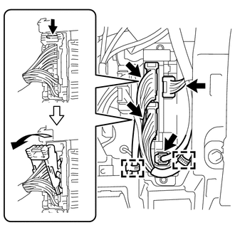
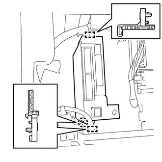
Remove the 2 clamps and disconnect each front side connector indicated as shown in the illustration (for LHD).
-
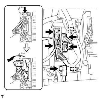
Remove the 2 clamps and disconnect each front side connector indicated as shown in the illustration (for RHD with Rear Fog Light).
-
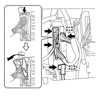
Remove the 2 clamps and disconnect each front side connector indicated as shown in the illustration (for RHD without Rear Fog Light).
-
Remove the screw of wire harness protector (for RHD).
-
Disengage the clamp and disconnect the wire harness protector (for RHD).
-
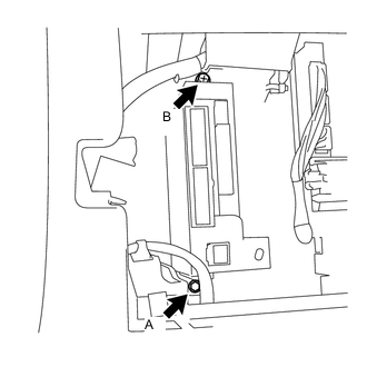
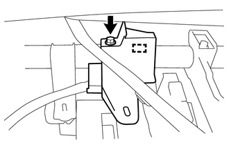
Remove the bolt A and the screw B indicated as shown in the illustration.
-
Disengage the claw, 2 clamps and disconnect the instrument panel junction block assembly.
-
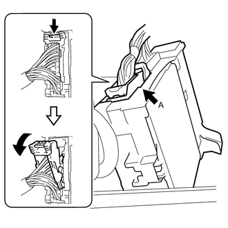
Disconnect the back side connector A indicated as shown in the illustration.
-
Text in illustration *a Lever Slide the lever to the upward.
-
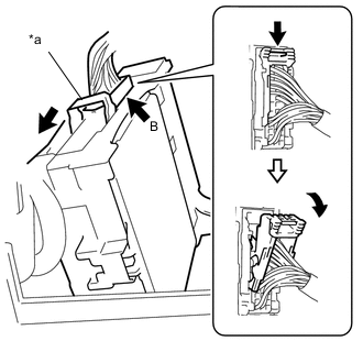
Disconnect the back side connector B indicated as shown in the illustration.
-
Remove the instrument panel junction block assembly.
-
-
REMOVE JUNCTION BLOCK BRACKET
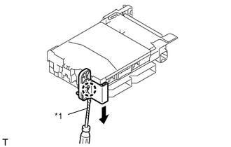
Text in illustration *1 Protective Tape
-
Using a screwdriver with its tip wrapped in protective tape, disengage the claw and remove the junction block bracket.
-
-
REMOVE JUNCTION BLOCK BRACKET
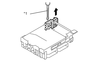
Text in illustration *1 Protective Tape
-
Using a screwdriver with its tip wrapped in protective tape, disengage the claw and remove the junction block bracket.
-
-
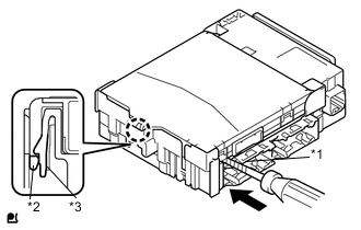
REMOVE MULTIPLEX NETWORK BODY ECU
-
Press the claw of the instrument panel junction block assembly side as shown in the illustration to release the lock.
-
With the instrument panel junction block assembly side, insert the screwdriver with its tip wrapped in protective tape between the multiplex network body ECU and the instrument panel junction block assembly.
Note
Use a blade screwdriver with a diameter of 5.0 to 6.3 mm (0.197 to 0.248 in.),and with a length of 90mm (3.543 in.) or more.
Text in illustration *1 Protective Tape *2 Multiplex Network Body ECU *3 Junction Block -
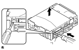
Text in illustration *1 Protective Tape Using the screwdriver with its tip wrapped with protective tape, carefully raise the multiplex network body ECU until the connector becomes disengaged.
Note
-
Do not twist the screwdriver to raise the multiplex network body ECU.
-
If any terminals of the connectors, locking parts or cases are deformed or damaged, replace the instrument panel junction block assembly or the multiplex network body ECU.
-
-
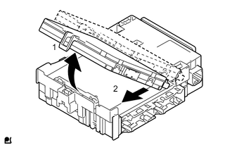
Raise the multiplex network body ECU as shown by arrow 1, and then pull it out as shown by arrow 2 in the illustration.
Note
Do not touch the multiplex network body ECU connector.
-