NAVIGATION SYSTEM, Diagnostic DTC:B1532
| DTC Code | DTC Name |
|---|---|
| B1532 | LVDS Signal Malfunction (from Extension Module) |
DESCRIPTION
| DTC No. | DTC Detection Condition | Trouble Area |
|---|---|---|
| B1532 | When one of the conditions below is met:
|
|
WIRING DIAGRAM

| *a | Radio and Display Receiver Assembly |
| *b | Navigation ECU |
| *c | LVDS Communication Line |
PROCEDURE
-
CHECK HARNESS AND CONNECTOR (NAVIGATION ECU POWER SOURCE)
-
Disconnect the T4 navigation ECU connector.
-
Measure the resistance according to the value(s) in the table below.
Standard Resistance Tester Connection Condition Specified Condition T4-2 (GND) - Body ground Always Below 1 Ω -
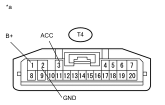
Text in Illustration *a Front view of wire harness connector
(to Navigation ECU)
Measure the voltage according to the value(s) in the table below.
Standard Voltage Tester Connection Condition Specified Condition T4-1 (B+) - T4-2 (GND) Always 11 to 14 V*1
9.5 to 14 V*2
T4-3 (ACC) - T4-2 (GND) Ignition switch ACC 11 to 14 V*1
9.5 to 14 V*2
-
*1: w/o Stop and Start System
-
*2: w/ Stop and Start System
Result Result Proceed to NG A OK B -
B 
REPLACE HARNESS AND CONNECTOR (LVDS COMMUNICATION LINE) Click here
A 
-
-
CHECK HARNESS AND CONNECTOR (RADIO AND DISPLAY RECEIVER ASSEMBLY - NAVIGATION ECU)
-
Disconnect the T3 radio and display receiver assembly connector.
-
Measure the resistance according to the value(s) in the table below.
Standard Resistance Tester Connection Condition Specified Condition T3-3 (ACC2) - T4-3 (ACC) Always Below 1 Ω T3-4 (+B2) - T4-1 (B+) Always Below 1 Ω T3-8 (GND2) - T4-2 (GND) Always Below 1 Ω T3-3 (ACC2) - Body ground Always 10 kΩ or higher T3-4 (+B2) - Body ground Always 10 kΩ or higher T3-8 (GND2) - Body ground Always 10 kΩ or higher
OK 
REPLACE RADIO AND DISPLAY RECEIVER ASSEMBLY Click here
NG
REPAIR OR REPLACE HARNESS AND CONNECTOR
-
-
REPLACE HARNESS AND CONNECTOR (LVDS COMMUNICATION LINE)
-
Replace the harness and connector (LVDS communication line).
-
Clear the DTCs Click here.
-
Recheck for DTCs and check if the same DTCs are output again.
OK No DTCs are output.
OK
END
NG
-
-
REPLACE NAVIGATION ECU
-
Replace the navigation ECU Click here.
-
Clear the DTCs Click here.
-
Recheck for DTCs and check if the same DTCs are output again.
OK No DTCs are output.
OK
END
NG
REPLACE RADIO AND DISPLAY RECEIVER ASSEMBLY Click here
-