NAVIGATION SYSTEM, Diagnostic DTC:B1579
| DTC Code | DTC Name |
|---|---|
| B1579 | Voice Recognition Microphone Disconnected |
DESCRIPTION
Microphone signal from the microphone amplifier assembly is sent to the radio and display receiver assembly.
Also, power is supplied from the radio and display receiver assembly to the microphone amplifier assembly.
If microphone signal is disconnected, this DTC is stored.
This DTC is stored when a malfunction occurs in a connected device.
| DTC No. | DTC Detection Condition | Trouble Area |
|---|---|---|
| B1579 | Telephone microphone signal is lost. |
|
WIRING DIAGRAM
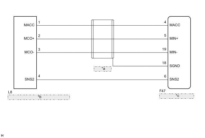
| *a | (Shielded) |
| *b | Map Light Assembly (Microphone Amplifier Assembly) |
| *c | Radio and Display Receiver Assembly |
PROCEDURE
-
CHECK MICROPHONE (OPERATION CHECK)
-
Enter the "Microphone Check" screen Click here.
-
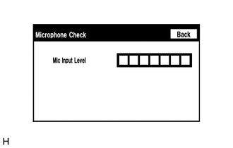
When voice is input into the microphone, check that the microphone input level meter changes according to the input voice.
OK Check result is normal.
OK 
REPLACE RADIO AND DISPLAY RECEIVER ASSEMBLY Click here
NG 
-
-
CHECK HARNESS AND CONNECTOR (RADIO AND DISPLAY RECEIVER ASSEMBLY - MAP LIGHT ASSEMBLY)
-
Disconnect the F47 radio and display receiver assembly connector.
-
Disconnect the L8 map light assembly connector.
-
Measure the resistance according to the value(s) in the table below.
Standard Resistance (Check for Open) Tester Connection Switch Condition Specified Condition F47-6 (SNS2) - L8-4 (SNS2) Always Below 1 Ω F47-4 (MACC) - L8-1 (MACC) Always Below 1 Ω F47-5 (MIN+) - L8-2 (MCO+) Always Below 1 Ω F47-19 (MIN-) - L8-3 (MCO-) Always Below 1 Ω Standard Resistance (Check for Short) Tester Connection Switch Condition Specified Condition F47-6 (SNS2) - Body ground Always 10 kΩ or higher F47-4 (MACC) - Body ground Always 10 kΩ or higher F47-5 (MIN+) - Body ground Always 10 kΩ or higher F47-19 (MIN-) - Body ground Always 10 kΩ or higher F47-18 (SGND) - Body ground Always 10 kΩ or higher
NG
REPAIR OR REPLACE HARNESS OR CONNECTOR
OK
-
-
CHECK RADIO AND DISPLAY RECEIVER ASSEMBLY
-
Reconnect the F47 radio and display receiver assembly connector.
-
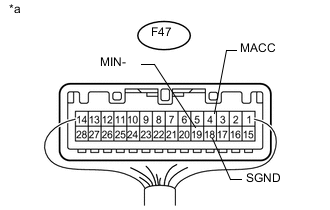
Text in Illustration *a Component with harness connected
(Radio and Display Receiver Assembly)
Measure the voltage according to the value(s) in the table below.
Standard Voltage Tester Connection Switch Condition Specified Condition F47-4 (MACC) - Body ground Ignition switch ACC 4 to 6 V -
Measure the resistance according to the value(s) in the table below.
Standard Resistance Tester Connection Condition Specified Condition F47-18 (SGND) - Body ground Always Below 1 Ω F47-19 (MIN-) - Body ground Always Below 1 Ω
NG
REPLACE RADIO AND DISPLAY RECEIVER ASSEMBLY Click here
OK
-
-
CHECK MICROPHONE AMPLIFIER ASSEMBLY
-
Measure the resistance according to the value(s) in the table below.
Standard Resistance Tester Connection Switch Condition Specified Condition L8-4 (SNS2) - L8-3 (MCO-) Always Below 1 Ω
NG
REPLACE MICROPHONE AMPLIFIER ASSEMBLY Click here
OK
-
-
CHECK MICROPHONE AMPLIFIER ASSEMBLY
-
Reconnect the F47 radio and display receiver assembly connector.
-
Reconnect the L8 map light assembly connector.
-
Turn the ignition switch to ACC.
-
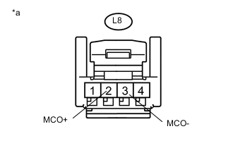
Text in Illustration *a Component with harness connected
(Map Light Assembly (Microphone Amplifier Assembly))
Connect an oscilloscope to terminals 2 (MCO+) and 3 (MCO-) of the L8 map light assembly connector.
-
Check the waveform of the microphone amplifier assembly using the oscilloscope.
Result Result Proceed to A waveform synchronized with the voice input to the map light assembly is output A A waveform synchronized with the voice input to the map light assembly is not output B
A
REPLACE RADIO AND DISPLAY RECEIVER ASSEMBLY Click here
B
REPLACE MICROPHONE AMPLIFIER ASSEMBLY Click here
-