RADIO ANTENNA CORD INSTALLATION
PROCEDURE
-
INSTALL NO. 2 ANTENNA CORD SUB-ASSEMBLY (except Glass Roof)
-
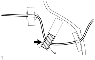
Align the No. 2 antenna cord sub-assembly 2 marking tapes to the markings on the roof headlining assembly to fix the No. 2 antenna cord sub-assembly with the 2 strips of adhesive tape, as shown in the illustration.
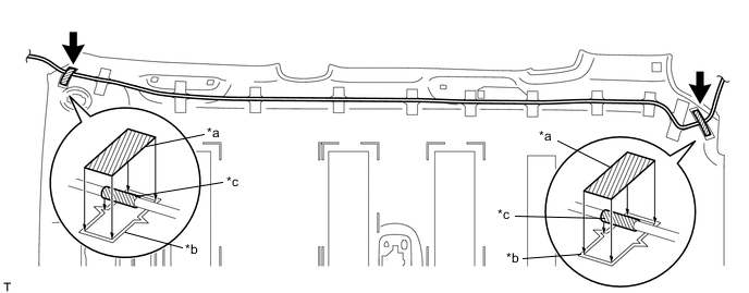
Text in Illustration *a Adhesive Tape *b Marking *c Marking Tape - - Note
Do not touch the adhesive surface when applying the tape to prevent adhesion failure.
-
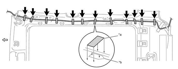
Install the No. 2 antenna cord sub-assembly to the roof headlining assembly with the 9 strips of adhesive tape, as shown in the illustration.
Note
Start applying the strips of adhesive tape from the vehicle front side.
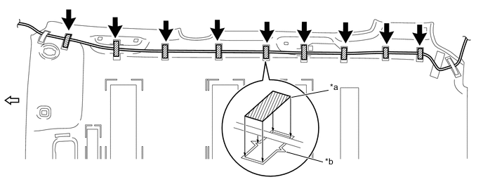
Text in Illustration *a Adhesive Tape *b Marking 
Vehicle Front Side - - -
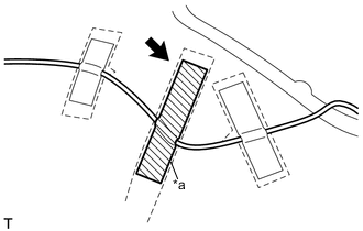
Text in Illustration *a Adhesive Tape Apply the adhesive tape to the extra part of the No. 2 antenna cord sub-assembly, as shown in the illustration.
-
-
INSTALL NO. 2 ANTENNA CORD SUB-ASSEMBLY (for Glass Roof)
-
Align the No. 2 antenna cord sub-assembly 2 marking tapes to the markings on the roof headlining assembly to fix the No. 2 antenna cord sub-assembly with the 2 strips of adhesive tape, as shown in the illustration.
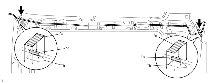
Text in Illustration *a Adhesive Tape *b Marking *c Marking Tape - - Note
Do not touch the adhesive surface when applying the tape to prevent adhesion failure.
-
Install the No. 2 antenna cord sub-assembly to the roof headlining assembly with the 12 strips of adhesive tape, as shown in the illustration.
Note
Start applying the strips of adhesive tape from the vehicle front side.
Text in Illustration *a Adhesive Tape *b Marking Vehicle Front Side - - -
Text in Illustration *a Adhesive Tape Apply the adhesive tape to the extra part of the No. 2 antenna cord sub-assembly, as shown in the illustration.
-
-
INSTALL ROOF HEADLINING ASSEMBLY
-
INSTALL ANTENNA CORD SUB-ASSEMBLY
-
Engage the 7 clamps.
-
Install the antenna cord sub-assembly with the bolt.
- Torque:
- 8.4 N*m { 86 kgf*cm, 74 in.*lbf }
-
Connect the antenna cord sub-assembly connector.
-
-
INSTALL UPPER INSTRUMENT PANEL SUB-ASSEMBLY
-
CONNECT CABLE TO NEGATIVE BATTERY TERMINAL
- Torque:
- 5.4 N*m { 55 kgf*cm, 48 in.*lbf }
-
INSPECT SRS WARNING LIGHT