STEERING COLUMN ASSEMBLY(for RHD) INSTALLATION

PROCEDURE
-
INSTALL STEERING COLUMN ASSEMBLY
-
Install the steering column assembly onto the instrument panel reinforcement assembly with the 2 nuts and new bolt.
- Torque:
- Bolt
- 36 N*m { 367 kgf*cm, 27 ft.*lbf }
- Nut
- 25 N*m { 255 kgf*cm, 18 ft.*lbf }
Note
-
Be sure there's no interference around the wire harness.
-
There are two different bolt sizes (12 mm (0.472 in.) or 14 mm (0.551 in.)) available.
-
Connect all the connectors and clamp the wire harnesses onto the steering column assembly bracket.
-
Connect the 2 steering column assembly connectors to the power steering ECU assembly.
-
Install the wire harness clamp to the power steering ECU assembly.
-
-
INSTALL STEERING SLIDING YOKE SUB-ASSEMBLY
-
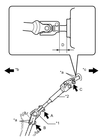
Text in Illustration *1 Steering Sliding Yoke Sub-assembly *2 No. 2 Steering Intermediate Shaft Assembly *a Matchmark *b Front of the Vehicle *c Rear of the Vehicle Tighten the bolt C while aligning the No. 2 steering intermediate shaft assembly with the position D as shown in the illustration.
Standard D 18.5 to 19.7 mm - Torque:
- 35 N*m { 360 kgf*cm, 26 ft.*lbf }
-
Align the matchmarks on steering sliding yoke sub-assembly and the steering gear assembly.
Tech Tips
When the steering sliding yoke sub-assembly is replaced with a new one, it has no matchmarks, so install it while the head of the bolt B faces the back of the vehicle as shown in the illustration.
-
Install bolt B.
- Torque:
- 35 N*m { 360 kgf*cm, 26 ft.*lbf }
-
Tighten bolt A.
- Torque:
- 35 N*m { 360 kgf*cm, 26 ft.*lbf }
-
-
INSTALL COLUMN HOLE COVER SILENCER SHEET
-
Install the column hole cover silencer sheet with the 2 clips.
-
Install the floor carpet.
-
-
INSTALL BRAKE PEDAL SUPPORT SUB-ASSEMBLY
-
INSTALL COMBINATION SWITCH ASSEMBLY
-
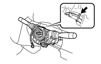
Install the combination switch assembly onto the steering column assembly with the clamp.
-
Connect all the connectors to the combination switch assembly.
-
-
INSTALL UPPER STEERING COLUMN COVER
-
Engage the claw to install the upper steering column cover.
-
-
INSTALL LOWER STEERING COLUMN COVER
-
Engage the 2 claws to install the lower steering column cover.
-
Install the 3 screws.
-
-
INSTALL STEERING COLUMN COVER SUPPORT (w/ Entry and Start System)
-
Engage the 4 claws and install the steering column cover support.
-
-
INSTALL STEERING WHEEL ASSEMBLY
-
INSTALL STEERING PAD
-
POSITION FRONT WHEELS FACING STRAIGHT AHEAD
-
CONNECT CABLE TO NEGATIVE BATTERY TERMINAL
- Torque:
- 5.4 N*m { 55 kgf*cm, 48 in.*lbf }
-
INSPECT SRS WARNING LIGHT
-
PERFORM CALIBRATION OF TORQUE SENSOR ZERO POINT