STEERING COLUMN ASSEMBLY(for RHD) DISASSEMBLY

PROCEDURE
-
REMOVE STEERING SLIDING YOKE SUB-ASSEMBLY
-
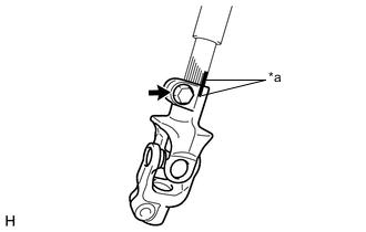
Text in Illustration *a Matchmark Place matchmarks on steering intermediate shaft assembly and the steering sliding yoke.
-
Remove bolt and steering sliding yoke from steering intermediate shaft assembly.
-
-
REMOVE NO. 2 STEERING INTERMEDIATE SHAFT ASSEMBLY
-
Remove the bolt and No. 2 steering intermediate shaft assembly from the steering column assembly.
-
-
REMOVE STEERING LOCK ACTUATOR ASSEMBLY (w/ Entry and Start System)
-
Fix the steering column assembly in a vise between aluminum plates.
Note
Do not overtighten the vise.
-
Using a drill, drill a hole in each of the steering lock set bolt, to insert a screw extractor.
-
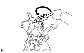
Using the screw extractor, remove the steering lock set bolt and remove the steering lock actuator assembly.
-
-
REMOVE UPPER STEERING COLUMN BRACKET ASSEMBLY (w/o Entry and Start System)
-
Fix the steering column assembly in a vise between aluminum plates.
Note
Do not overtighten the vise.
-
Using a drill, drill a hole in each of the steering lock set bolt, to insert a screw extractor.
-
Using the screw extractor, remove the steering lock set bolt and remove the steering column upper with switch bracket assembly.
-
-
REMOVE UN-LOCK WARNING SWITCH ASSEMBLY (w/o Entry and Start System)
-
Insert the key.
-
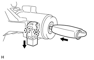
Remove the un-lock warning switch assembly by releasing the 2 claws.
Tech Tips
Slide the un-lock warning switch assembly, in the direction shown by the arrow in the illustration, to remove it.
-
-
REMOVE KEY INTER LOCK SOLENOID (w/o Entry and Start System)
-
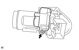
Remove the screw and key lock solenoid from the upper steering column bracket assembly.
-
-
REMOVE IGNITION SWITCH LOCK CYLINDER ASSEMBLY (w/o Entry and Start System)
-
Turn the ignition switch to ACC.
-
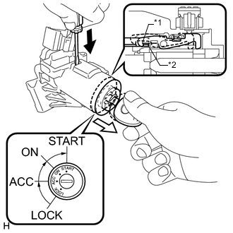
Text in Illustration *1 Claw *2 Stopper 
Push 
Pull Insert the tip of a screwdriver into the hole in the upper steering column bracket assembly, as shown in the illustration, and pull the ignition switch lock cylinder assembly out until its claw comes into contact with the stopper of the upper steering column bracket assembly.
Note
Pull the ignition switch lock cylinder assembly out until the claw comes into contact with the stopper of the upper steering column bracket assembly. Otherwise, the following procedure cannot be conducted properly.
-
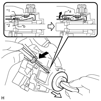
Text in Illustration *1 Claw *2 Stopper *a Claw disengaged *b Driver Insertion Hole Tilt Pull out Insert the tip of a screwdriver into the hole in the steering column bracket and tilt it downward, as shown in the illustration, to disengage the claw on the ignition switch lock cylinder. Then pull out the ignition switch lock cylinder.
-
-
REMOVE IGNITION OR STARTER SWITCH ASSEMBLY (w/o Entry and Start System)
-
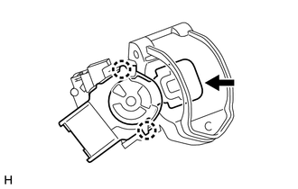
Disengage the 2 claws and remove the ignition or starter switch assembly from the upper steering column bracket assembly.
Note
-
Be sure to start operation while the ignition or starter switch assembly faces upward, and while the upper steering column bracket assembly faces downward.
-
Check the press in condition of the arrow inner part, If the inner part has loose fit, Replace the upper steering column bracket assembly.
-
-
-
REMOVE NO. 1 STEERING COLUMN PROTECTOR (for Manual Transmission)
-
Remove the bolt and No. 1 steering column protector.
-