STEERING COLUMN ASSEMBLY(for LHD) REASSEMBLY

PROCEDURE
-
INSTALL IGNITION OR STARTER SWITCH ASSEMBLY (w/o Entry and Start System)
-
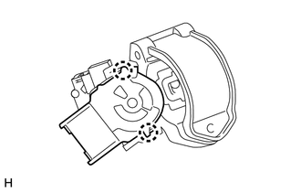
Engage the 2 claws to install the ignition or starter switch assembly onto the upper steering column bracket assembly.
-
-
INSTALL KEY INTER LOCK SOLENOID (w/o Entry and Start System)
-
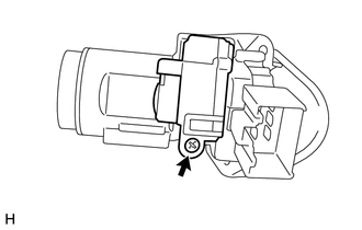
Install the key inter lock solenoid onto the upper steering column bracket assembly with the screw.
-
-
INSTALL UN-LOCK WARNING SWITCH ASSEMBLY (w/o Entry and Start System)
-
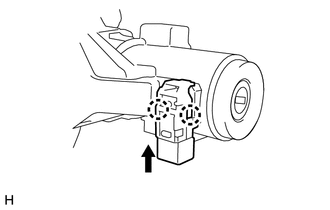
Engage the 2 claws to install the un-lock warning switch assembly onto the upper steering column bracket assembly.
Tech Tips
Slide the un-lock warning switch assembly, in the direction shown by the arrow in the illustration, to install it.
-
-
INSTALL IGNITION SWITCH LOCK CYLINDER ASSEMBLY (w/o Entry and Start System)
-
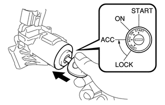
Turn the ignition switch to ACC.
-
Install the ignition switch lock cylinder assembly into the upper steering column bracket assembly.
-
Make sure that the ignition switch lock cylinder assembly is securely fixed onto the ignition switch lock cylinder assembly.
-
-
INSTALL UPPER STEERING COLUMN BRACKET ASSEMBLY (w/o Entry and Start System)
-
Set the steering column assembly in a vise between aluminum plates.
Note
Do not overtighten the vise.
-
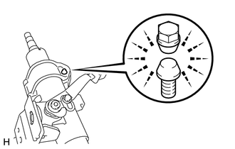
Install the steering column upper with switch bracket assembly with new steering lock set bolt, and then tighten the bolts until their heads come off.
-
-
INSTALL STEERING LOCK ACTUATOR ASSEMBLY (w/ Entry and Start System)
-
Set the steering column assembly in a vise between aluminum plates.
Note
Do not overtighten the vise.
-
Install the steering lock actuator assembly with new steering lock set bolt, and then tighten the bolts until their heads come off.
-
-
INSTALL NO. 2 STEERING INTERMEDIATE SHAFT ASSEMBLY
-
Align the matchmarks on No. 2 steering intermediate shaft assembly and the steering column assembly and provisionally install them with the bolt.
Tech Tips
When either the steering column assembly or the No. 2 steering intermediate shaft assembly is replaced with a new one, they have no matchmarks, so align the marking (pink) on the steering column assembly shaft with the slit of the No. 2 steering intermediate shaft assembly, and install them.
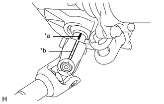
Text in Illustration *a Matchmark (Pink) *b Slit
-
-
INSTALL STEERING SLIDING YOKE SUB-ASSEMBLY
-
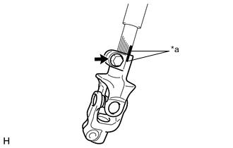
Text in Illustration *a Matchmark Align the matchmarks on No. 2 steering intermediate shaft assembly and the steering sliding yoke and provisionally install them with the bolt.
-