STEERING SYSTEM ADJUSTMENT
PROCEDURE
-
ADJUST STEERING WHEEL OFF CENTER
-
Inspect steering wheel off center.
-
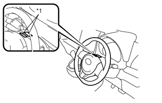
Text in Illustration *1 Masking Tape Apply masking tape on the top center of the steering wheel and steering column upper cover.
-
Drive the vehicle in a straight line for 100 meters at a constant speed of 56 km/h (35 mph), while holding the steering wheel to maintain the course.
-
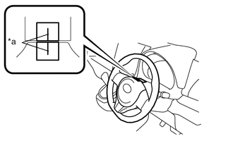
Text in Illustration *a Marked Line Draw a line on the masking tape as shown in the illustration.
-
Turn the steering wheel to the center position.
Tech Tips
Look at the upper surface of the steering wheel, steering spoke, and SRS airbag line to find the center position.
-
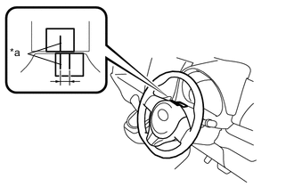
Text in Illustration *a Marked Line Draw a new line on the masking tape on the steering wheel as shown in the illustration.
-
Measure the distance between the 2 lines on the masking tape on the steering wheel.
-
Convert the measured distance to steering angle.
Standard Measured distance 1 mm (0.0397 in.) = Steering angle approximately 1 deg. Tech Tips
Make a note of the steering angle.
-
-
Adjust steering angle.
-
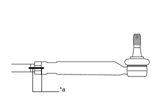
Text in Illustration *a Matchmark Draw a matchmarks on the RH and LH tie rod ends and rack ends respectively where it can be easily seen.
-
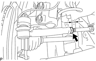
Using a paper gauge, measure the distance from the RH and LH tie rod ends to the rack end screws.
Tech Tips
-
Measure both the RH and LH sides.
-
Make a note of the measured values.
-
-
Remove the RH and LH boot clips from the rack boots.
-
Loosen the RH and LH lock nuts.
-
Turn the RH and LH rack ends by the same amount (but in different directions) according to the steering angle.
Standard 1 turn (360 deg.) of rack end (1.5 mm (0.0591 in.) horizontal movement) = 10.8 deg. of steering angle -
Tighten the RH and LH lock nuts to the specified torque.
- Torque:
- 75 N*m { 765 kgf*cm, 55 ft.*lbf }
Note
Make sure that the difference in length between the RH and LH tie rod ends and rack end screws is within 1.5 mm (0.0591 in.).
-
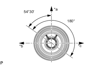
Text in Illustration *a Upper Side *b Front Side *c Rear Side Using pliers, install the RH and LH boot clips as shown in the illustration.
Note
Make sure that the rack boots are not twisted.
-
-