STEERING LOCK SYSTEM Unable to Unlock Steering Wheel (Engine cannot Start)
DESCRIPTION
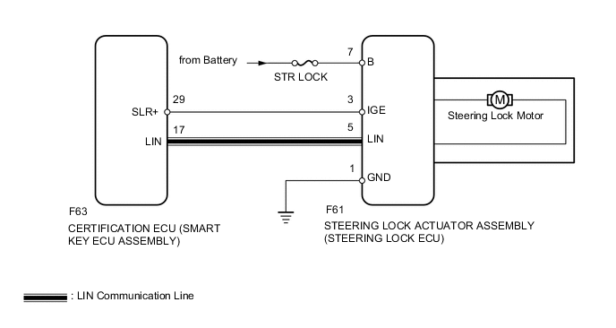
The steering lock actuator activates the steering lock motor and moves the lock bar into the steering column to lock the steering wheel.
The steering may not unlock when the lock bar gets stuck in the lock hole of the steering column. In this case, if an engine start operation is performed while shaking the steering wheel in the same manner as is done for a vehicle with a mechanical key, the lock bar will be unlocked. If the certification ECU (smart key ECU assembly), ID code box (immobiliser code ECU)* or ECM is replaced, the system needs to be initialized. Otherwise, the steering cannot be unlocked and the engine cannot be started, refer to the Service Bulletin.
*: except 1NZ-FE
WIRING DIAGRAM
CAUTION / NOTICE / HINT
Note
-
When using the intelligent tester with the engine switch off, perform either of the following: 1) Turn a courtesy light switch on and off at intervals of 1.5 seconds or less until communication between the intelligent tester and vehicle begins, or 2) connect the intelligent tester to the vehicle and select "MANUAL" from the initial screen on the intelligent tester, and then select "KEY REGIST" under Model Code.
-
Perform either of the following operations to lock/unlock the steering:
-
To unlock the steering, carry the key and turn the engine switch on (ACC) or on (IG) while the shift lever is in P*1 or N*2.
-
To lock the steering, turn the engine switch off with the shift lever in P*1 or N*2, and then open a door.
-
The steering lock system uses LIN communication. First perform the inspections in "How to Proceed with Troubleshooting" to confirm that there are no communication malfunctions before proceeding with troubleshooting Click here.
-
After completing repairs, confirm that the problem does not occur.
-
Make sure that no DTCs are output. If any DTCs are output, proceed to the Diagnostic Trouble Code Chart Click here.
-
Inspect the fuses for circuits related to this system before performing the following inspection procedure.
-
Before replacing the steering lock actuator assembly (steering lock ECU), certification ECU (smart key ECU assembly) or ID code box (immobiliser code ECU)*3, refer to the Service Bulletin.
-
When disconnecting the cable from the negative (-) battery terminal, some systems need to be initialized after the cable is reconnected Click here.
-
If the steering lock actuator assembly (steering lock ECU) is replaced, be sure to confirm that the steering is unlocked by turning the steering wheel to the left and right before starting the engine. If the steering is locked for any reason, open and close a door with the engine switch off, and then unlock the steering by pressing the engine switch. This prevents the engine from starting while the steering is locked.
Tech Tips
| Problem Symptom | Data List Item | Active Test Item |
|---|---|---|
| Unable to unlock steering wheel (Engine cannot start) |
Entry&Start |
- |
*1: for CVT
*2: for Multi-mode Manual Transaxle
*3: except 1NZ-FE
PROCEDURE
-
CHECK ENGINE SWITCH (SWITCH CONDITION)
-
Check the power source mode change.
-
When the key is inside the vehicle and the shift lever is in P, check that pressing the engine switch with the brake pedal*1 or clutch pedal*2 released causes the power source mode to change as follows:
OK Off → on (ACC) → on (IG) → off
-
*1: for CVT and Multi-mode Manual Transaxle
-
*2: for Manual Transaxle
-
NG 
GO TO ENTRY AND START SYSTEM (FOR START FUNCTION) (PROBLEM SYMPTOMS TABLE) Click here
OK 
-
-
READ VALUE USING INTELLIGENT TESTER (UNLOCK REQUEST RECEIVE)
-
Use the Data List to check if the steering lock command is functioning properly.
Entry&Start Tester Display Measurement Item/Range Normal Condition Diagnostic Note Unlock Request Receive Reception state of steering unlock command signal determined by certification ECU (smart key ECU assembly) and sent to ID code box (immobiliser code ECU)* /NG or OK
Tech Tips
The reception state is maintained for 10 seconds.
OK: Within 10 seconds of turning engine switch on (IG) or on (ACC) or starting engine
NG: Except above
When 10 seconds or more elapse after the signal is received, the item changes to "NG". *: except 1NZ-FE
OK Within 10 seconds of turning the engine switch on (ACC) or on (IG) or starting the engine, the Data List item changes to "OK".
NG 
READ VALUE USING INTELLIGENT TESTER (S CODE CHECK) Click here
OK
-
-
CHECK HARNESS AND CONNECTOR (STEERING LOCK ECU - BATTERY AND BODY GROUND)
-
Disconnect the F61 steering lock actuator assembly (steering lock ECU) connector.
-
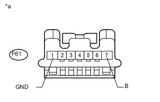
Text in Illustration *a Front view of wire harness connector
(to steering lock actuator assembly (steering lock ECU))
Measure the resistance and voltage according to the value(s) in the table below.
Standard Resistance Tester Connection Condition Specified Condition F61-1 (GND) - Body ground Always Below 1 Ω Note
If the result is not as specified, check for looseness in the connection which leads to ground.
Standard Voltage Tester Connection Condition Specified Condition F61-7 (B) - Body ground Always 11 to 14 V
NG
REPAIR OR REPLACE HARNESS OR CONNECTOR
OK
-
-
INSPECT STEERING LOCK ECU (IGE VOLTAGE)
-
Disconnect the F61 steering lock actuator assembly (steering lock ECU) connector.
-
Measure the resistance according to the value(s) in the table below.
Standard Resistance Tester Connection Condition Specified Condition F61-1 (GND) - Body ground Always Below 1 Ω -
Reconnect the F61 steering lock actuator assembly (steering lock ECU) connector.
-
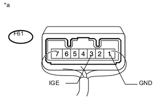
Text in Illustration *a Component with harness connected
(Steering lock actuator assembly (Steering lock ECU))
Measure the voltage according to the value(s) in the table below.
Standard Voltage Tester Connection Condition Specified Condition F61-3 (IGE) - F61-1 (GND) Specified condition is checked after performing the following:
-
Turn the engine switch off
-
Turn the engine switch on (ACC or IG)
-
Motor activated: Below 1 V
-
Motor not activated: 11 to 14 V
Specified condition is checked after performing the following:
-
Move the shift lever to P*1 or N*2
-
Turn the engine switch off
-
Open the driver door
-
Motor activated: Below 1 V
-
Motor not activated: 11 to 14 V
*1: for CVT
*2: for Multi-mode Manual Transaxle
Tech Tips
When the steering lock is activated and the engine switch is turned on (IG), the steering lock motor activates to release the steering lock. The motor operation occurs for 2 to 15 seconds.
Result Result Proceed to NG A OK (for LHD) B OK (for RHD) C -
A
REPAIR OR REPLACE HARNESS OR CONNECTOR
B
REPLACE STEERING LOCK ACTUATOR ASSEMBLY (STEERING LOCK ECU) Click here
C
REPLACE STEERING LOCK ACTUATOR ASSEMBLY (STEERING LOCK ECU) Click here
-
-
READ VALUE USING INTELLIGENT TESTER (S CODE CHECK)
-
Use the Data List to check if S code certification is functioning properly.
Entry&Start Tester Display Measurement Item/Range Normal Condition Diagnostic Note S Code Check Verification result between certification ECU (smart key ECU assembly) and ID code box (immobiliser code ECU)* /NG or OK OK: Verification result normal
NG: Verification result abnormal
- OK OK is displayed on the intelligent tester. Tech Tips
Reasons for verification failure:
-
The certification ECU (smart key ECU assembly) or ID code box (immobiliser code ECU)* is malfunctioning.
-
There is a problem with the communication between ECUs.
-
An ECU is replaced, but is not registered.
-
An ECU is replaced with an ECU which has a code already stored in it.
*: except 1NZ-FE
Result Result Proceed to OK A NG (except 1NZ-FE) B NG (for 1NZ-FE) C -
B
REPLACE ID CODE BOX Click here
C
REPLACE CERTIFICATION ECU (SMART KEY ECU ASSEMBLY)
A
-
-
READ VALUE USING INTELLIGENT TESTER (L CODE CHECK)
-
Use the Data List to check if L code certification is functioning properly.
Entry&Start Tester Display Measurement Item/Range Normal Condition Diagnostic Note L Code Check Verification result between ID code box (immobiliser code ECU)*1 or certification ECU (smart key ECU assembly)*2 and steering lock actuator assembly/NG or OK OK: Verification result normal
NG: Verification result abnormal
- OK OK is displayed on the intelligent tester. Tech Tips
Reasons for verification failure:
-
The steering lock actuator assembly (steering lock ECU)*2 or ID code box (immobiliser code ECU)*1 is malfunctioning.
-
There is a problem with the communication between ECUs.
-
An ECU is replaced, but is not registered.
-
An ECU is replaced with an ECU which has a code already stored in it.
*1: except 1NZ-FE
*2: for 1NZ-FE
Result Result Proceed to OK A NG (except 1NZ-FE) B NG (for 1NZ-FE) C -
B
REPLACE ID CODE BOX Click here
C
REPLACE STEERING LOCK ACTUATOR ASSEMBLY (STEERING LOCK ECU) Click here
A
-
-
REPLACE STEERING LOCK ACTUATOR ASSEMBLY (STEERING LOCK ECU)
-
Replace the steering lock actuator assembly (steering lock ECU) with a new one.
-
Perform the registration procedures (Refer to Service Bulletin for registration).
-
Turn the engine switch on (IG).
-
Operate the steering wheel and check the steering condition.
OK Steering is unlocked.
OK
END
NG
REPLACE CERTIFICATION ECU (SMART KEY ECU ASSEMBLY)
-
-
REPLACE ID CODE BOX
-
Replace the id code box (immobiliser code ECU)* with a new one.
-
Perform the registration procedures (Refer to Service Bulletin for registration).
-
Use the Data List to check if S code certification is functioning properly again.
Entry&Start Tester Display Measurement Item/Range Normal Condition Diagnostic Note S Code Check Verification result between certification ECU (smart key ECU assembly) and ID code box (immobiliser code ECU)* /NG or OK OK: Verification result normal
NG: Verification result abnormal
- *: except 1NZ-FE
OK OK is displayed on the intelligent tester.
OK
END
NG
REPLACE CERTIFICATION ECU (SMART KEY ECU ASSEMBLY)
-
-
REPLACE ID CODE BOX
-
Replace the id code box (immobiliser code ECU)* with a new one.
-
Perform the registration procedures (Refer to Service Bulletin for registration).
-
Use the Data List to check if L code certification is functioning properly again.
Entry & Start Tester Display Measurement Item/Range Normal Condition Diagnostic Note L Code Check Verification result between ID code box (immobiliser code ECU)* and steering lock actuator assembly/NG or OK OK: Verification result normal
NG: Verification result abnormal
- Result Result Proceed to OK A NG (for LHD) B NG (for RHD) C *: except 1NZ-FE
A
END
B
REPLACE STEERING LOCK ACTUATOR ASSEMBLY (STEERING LOCK ECU) Click here
C
REPLACE STEERING LOCK ACTUATOR ASSEMBLY (STEERING LOCK ECU) Click here
-
-
REPLACE STEERING LOCK ACTUATOR ASSEMBLY (STEERING LOCK ECU)
-
Replace the steering lock actuator assembly (steering lock ECU) with a new one.
-
Perform the registration procedures.
-
Use the Data List to check if L code certification is functioning properly again.
Entry & Start Tester Display Measurement Item/Range Normal Condition Diagnostic Note L Code Check Verification result between ID code box (immobiliser code ECU)* and steering lock actuator assembly/NG or OK OK: Verification result normal
NG: Verification result abnormal
- *: except 1NZ-FE
OK
END
NG
REPLACE CERTIFICATION ECU (SMART KEY ECU ASSEMBLY)
-