POWER STEERING SYSTEM, Diagnostic DTC:C1553
| DTC Code | DTC Name |
|---|---|
| C1553 | PIG Power Supply Overvoltage |
DESCRIPTION
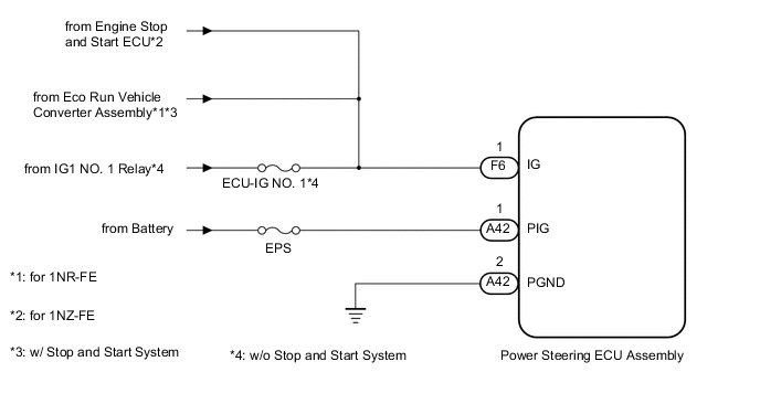
If the power steering ECU assembly determines that the motor power source voltage and the IG voltage are not within the specified range, it stops the power assist as a fail-safe function.
| DTC No. | DTC Detection Condition | Trouble Area |
|---|---|---|
| C1553 |
|
|
WIRING DIAGRAM
CAUTION / NOTICE / HINT
Note
-
If the power steering ECU assembly has been replaced, perform the torque sensor zero point calibration Click here.
-
Inspect the fuses for circuits related to this system before performing the following inspection procedure.
PROCEDURE
-
CHECK HARNESS AND CONNECTOR (IG)
-
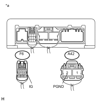
Text in illustration *a Rear view of wire harness connector
(to Power Steering ECU Assembly)
Disconnect the A42 and F6 power steering ECU assembly connectors.
-
Measure the voltage according to the value(s) in the table below.
Standard Voltage Tester Connection Switch Condition Specified Condition F6-1 (IG) - A42-2 (PGND) Ignition switch ON 11 to 14 V Result Result Proceed to OK A NG (w/o Stop and Start System) B NG (w/ Stop and Start System for 1NR-FE) C NG (for 1NZ-FE) D
B 
REPAIR OR REPLACE HARNESS OR CONNECTOR
C
GO TO STOP AND START SYSTEM Click here
D
GO TO STOP AND START SYSTEM Click here
A 
-
-
CHECK HARNESS AND CONNECTOR (PIG)
-
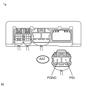
Text in illustration *a Rear view of wire harness connector
(to Power Steering ECU Assembly)
Disconnect the A42 power steering ECU assembly connector.
-
Measure the voltage according to the value(s) in the table below.
Standard Voltage Tester Connection Condition Specified Condition A42-1 (PIG) - A42-2 (PGND) Always 11 to 14 V Result Result Proceed to NG A OK (for LHD) B OK (for RHD) C
A
REPAIR OR REPLACE HARNESS OR CONNECTOR
B
REPLACE POWER STEERING ECU ASSEMBLY Click here
C
REPLACE POWER STEERING ECU ASSEMBLY Click here
-