REAR BRAKE(for Disc Type) INSTALLATION

PROCEDURE
-
INSTALL REAR DISC
-
Align the matchmarks of the disc and axle hub and install the disc.
Note
When replacing the disc with a new one, select the installation position where the rear disc has minimum runout.
-
-
INSTALL REAR DISC BRAKE CYLINDER MOUNTING
-
Install the rear disc brake cylinder mounting to the axle beam with the 2 bolts.
- Torque:
- 57 N*m { 585 kgf*cm, 42 ft.*lbf }
-
-
INSTALL REAR DISC BRAKE BUSH DUST BOOT
-
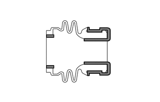
Apply lithium soap base glycol grease to the entire circumference of 2 new rear disc brake bush dust boots as shown in the illustration.
Text in Illustration 
Lithium Soap Base Glycol Grease Tech Tips
Apply at least 0.3 g (0.01 oz.) of lithium soap base glycol grease to each rear disc brake bush dust boot.
-
Install the 2 rear disc brake bush dust boots onto the rear disc brake cylinder mounting.
-
-
INSTALL REAR DISC BRAKE PAD GUIDE PIN
-
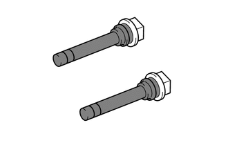
Apply a light layer of lithium soap base glycol grease to the entire circumference of the 2 rear disc brake pad guide pins as shown in the illustration.
Text in Illustration Lithium Soap Base Glycol Grease -
Install the 2 rear disc brake pad guide pins onto the rear disc brake cylinder mounting.
-
-
INSTALL REAR DISC BRAKE PAD SUPPORT PLATE
-
Install the No. 1 rear disc brake pad support plate and No. 2 rear disc brake pad support plate to the rear disc brake cylinder mounting.
Note
Be sure to install each rear disc brake pad support plate in the correct position and direction.
-
-
INSTALL REAR DISC BRAKE ANTI SQUEAL SHIM KIT
-
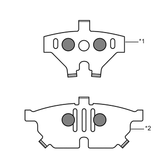
Text in Illustration *1 No. 1 Rear Disc Brake Anti Squeal Shim (Inner) *2 No. 1 Rear Disc Brake Anti Squeal Shim (Outer) Disc Brake Grease Apply disc brake grease to the inside of the 2 No. 1 rear disc brake anti squeal shims as shown in the illustration.
-
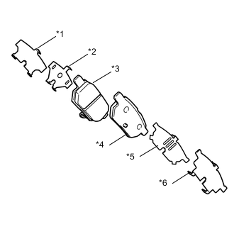
Text in Illustration *1 No. 2 Rear Disc Brake Anti Squeal Shim (Inner) *2 No. 1 Rear Disc Brake Anti Squeal Shim (Inner) *3 Rear Disc Brake Pad (w/ Indicator) *4 Rear Disc Brake Pad *5 No. 1 Rear Disc Brake Anti Squeal Shim (Outer) *6 No. 2 Rear Disc Brake Anti Squeal Shim (Outer) Install the 2 No. 1 rear disc brake anti squeal shims and 2 No. 2 rear disc brake anti squeal shims to each brake pad.
Note
-
When replacing worn pads, the anti squeal shims must be replaced together with the pads.
-
Apply disc brake grease to the area that contacts the anti squeal shim.
-
Disc brake grease may seep out slightly from the areas where the anti squeal shims are installed.
-
Make sure that disc brake grease is not applied onto the lining surface.
-
-
-
INSTALL REAR DISC BRAKE PAD KIT (PAD ONLY)
-
Install the 2 rear disc brake pads onto the rear disc brake cylinder mounting.
Note
There should be no oil or grease on the friction surfaces of the disc brake pads or the rear disc.
-
-
INSTALL REAR DISC BRAKE CYLINDER ASSEMBLY
-
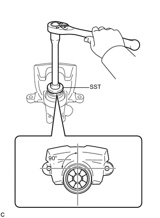
To compensate for pad wear when reusing the pad, use SST to push and turn the piston (LH side: counterclockwise, RH side: clockwise) to the position where the protrusion on the pad lines up properly with the piston groove.
- SST
- 09719-12010 ( 09719-01030 )
Note
Place the disc between the 2 brake pads and determine the piston return value.
-
Hold the rear disc brake pad guide pin, and install the rear disc brake cylinder assembly onto the rear disc brake cylinder mounting with the 2 bolts.
- Torque:
- 34 N*m { 350 kgf*cm, 25 ft.*lbf }
-
-
CONNECT REAR BRAKE FLEXIBLE HOSE
-
Connect the flexible hose to the rear disc brake cylinder assembly with the union bolt and a new gasket.
- Torque:
- 30 N*m { 310 kgf*cm, 22 ft.*lbf }
Tech Tips
Install the flexible hose lock securely into the lock hole in the disc brake cylinder.
-
-
CONNECT NO. 3 PARKING BRAKE CABLE ASSEMBLY
-
Install the casing cap clip onto the rear disc brake cylinder guide.
-
Connect the cable end to the rear disc brake cylinder operation lever.
-
-
FILL RESERVOIR WITH BRAKE FLUID
-
BLEED CLUTCH LINE
-
for 1NR-FE Click here
-
for 1ND-TV Click here
-
-
BLEED CLUTCH LINE (for Multi-Mode Manual Transaxle)
(See page CLUTCH > CLUTCH SYSTEM (for EC65A) > BLEEDING > BLEED CLUTCH LINE)
-
BLEED BRAKE MASTER CYLINDER SUB-ASSEMBLY
-
BLEED BRAKE LINE
-
BLEED BRAKE ACTUATOR ASSEMBLY (w/ VSC)
-
INSPECT FOR BRAKE FLUID LEAK
-
INSPECT BRAKE FLUID LEVEL
-
ADJUST PARKING BRAKE LEVER TRAVEL
-
INSTALL REAR WHEEL
- Torque:
- 103 N*m { 1050 kgf*cm, 76 ft.*lbf }
-
INSTALL REAR CONSOLE BOX