BRAKE PEDAL(for RHD) ADJUSTMENT
PROCEDURE
-
INSPECT AND ADJUST BRAKE PEDAL
-
Inspect the brake pedal type (for 1NZ-FE).
-
Remove the brake pedal pad.
-
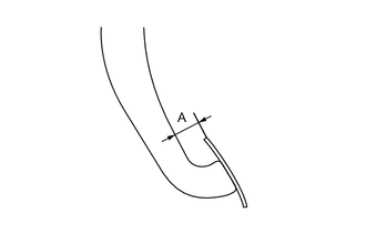
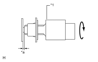
Measure the dimension A as shown in the illustration to determine the brake pedal type.
Dimension A Brake Pedal Type Dimension A for 1NZ-FE Type A 11.9 mm (0.469 in.) for 1NZ-FE Type B 18 mm (0.709 in.) -
Install the brake pedal pad.
-
-
Inspect the brake pedal height.
-
Remove the front door scuff plate RH. Click here
-
Remove the cowl side trim board RH. Click here
-
Remove the No. 2 dash panel insulator pad.
-
Turn back carpet.
-
Inspect brake pedal height.
Pedal height from floor panel Brake Pedal Type Pedal Height except 1NZ-FE 113.5 to 123.5 mm
(4.47 to 4.86 in.)
for 1NZ-FE Type A 107.3 to 117.3 mm
(4.22 to 4.62 in.)
for 1NZ-FE Type B 111.9 to 121.9 mm
(4.41 to 4.80 in.)
If the pedal height is incorrect, adjust it.
Tech Tips
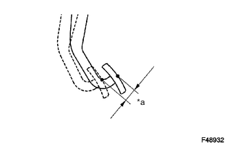
Measure the pedal height between the floor base surface and the pedal as shown in the illustration.
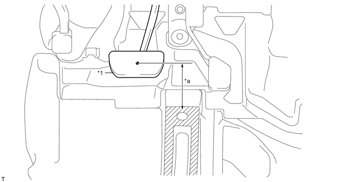
Text in Illustration *1 Brake Pedal - - *a Pedal Height - - 
Measuring Plane - -
-
-
Adjust the brake pedal height.
-
Disconnect the connector from the stop light switch.
-
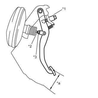
Text in Illustration *1 Stop Light Switch Assembly *2 Push Rod *3 Push Rod Lock Nut *a Pedal Height Turn the stop light switch counterclockwise and remove the stop light switch.
-
Loosen the push rod lock nut.
-
Adjust the pedal height by turning the pedal push rod.
Pedal height from floor panel Brake Pedal Type Pedal Height except 1NZ-FE 113.5 to 123.5 mm
(4.47 to 4.86 in.)
for 1NZ-FE Type A 107.3 to 117.3 mm
(4.22 to 4.62 in.)
for 1NZ-FE Type B 111.9 to 121.9 mm
(4.41 to 4.80 in.)
-
Tighten the push rod lock nut.
- Torque:
- 26 N*m { 265 kgf*cm, 19 ft.*lbf }
-
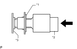
Text in Illustration *1 Adjuster *2 Stop Light Switch Assembly *3 Brake Pedal Insert the stop light switch into the adjuster until it just touches the brake pedal.
Note
Do not depress the brake pedal.
-
Text in Illustration *1 Stop Light Switch Assembly *a Stop Light Switch Clearance Make a quarter turn clockwise to install the stop light switch.
Note
Do not depress the brake pedal.
Tech Tips
The turning torque for installing the stop light switch:
- Torque:
- 1.5 N*m { 15 kgf*cm, 13 in.*lbf }
- or less
-
Check the stop light switch clearance.
Stop light switch clearance 0.5 to 2.6 mm (0.020 to 0.102 in.) -
Connect the connector to the stop light switch.
-
-
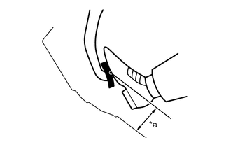
Text in Illustration *a Pedal Free Play Inspect the brake pedal free play.
-
Stop the engine and depress the brake pedal several times until there is no vacuum left in the booster.
-
Push in the pedal until a slight resistance is felt. Measure the distance as shown.
Pedal free play 1.0 to 6.0 mm (0.0394 to 0.236 in.) If incorrect, troubleshoot the brake system.
-
-
Inspect the brake pedal reserve distance.
Tech Tips
Measure the distance at the same point used for the brake pedal height inspection.
-
Remove the front door scuff plate RH. Click here
-
Remove the cowl side trim board RH. Click here
-
Remove the No. 2 dash panel insulator pad.
-
Turn back carpet.
-
Text in Illustration *a Reserve Distance Release the parking brake lever. With the engine running, depress the pedal and measure the pedal reserve distance as shown.
Pedal reserve distance from floor at 300 N (31 kgf, 67.4 lbf) Brake Pedal Type Pedal Reserve Distance except 1NZ-FE More than 79 mm (3.11 in.) for 1NZ-FE Type A More than 78 mm (3.07 in.) for 1NZ-FE Type B More than 80 mm (3.15 in.) Tech Tips
Sound and resistance from the brake booster when the brake pedal is depressed without a vacuum does not indicate a problem.
If incorrect, troubleshoot the brake system.
-
-