BRAKE ACTUATOR(for LHD) INSTALLATION
PROCEDURE
-
INSTALL BRAKE ACTUATOR BOLT CUSHION
-
Install the 3 brake actuator bolt cushions to the brake actuator bracket assembly.
-
-
INSTALL BRAKE ACTUATOR CASE COLLAR
-
Install the 3 brake actuator case collars to the brake actuator bolt cushion.
-
-
INSTALL NO. 1 BRAKE ACTUATOR BRACKET (for CVT)
-
Install the No. 1 brake actuator bracket with the 3 bolts to the side member.
- Torque:
- 19 N*m { 194 kgf*cm, 14 ft.*lbf }
-
-
INSTALL BRAKE ACTUATOR BRACKET ASSEMBLY
-
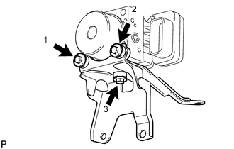
Install the actuator bracket with the 3 bolts in the sequence shown in the illustration.
- Torque:
- 5.4 N*m { 55 kgf*cm, 48 in.*lbf }
Note
-
Do not remove the hole plug before connecting the brake tube. New actuators are filled with brake fluid.
-
Do not carry with the connector part of an actuator.
-
-
INSTALL BRAKE ACTUATOR ASSEMBLY (except CVT)
-
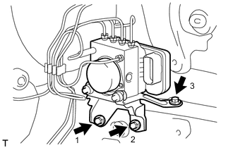
Install the brake actuator with bracket with the 3 bolts in the sequence shown in the illustration.
- Torque:
- 19 N*m { 194 kgf*cm, 14 ft.*lbf }
Note
Do not damage the brake tubes or wire harness.
-
-
INSTALL BRAKE ACTUATOR ASSEMBLY (for CVT)
-
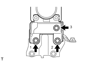
Install the brake actuator with bracket with the 3 bolts in the sequence shown in the illustration.
- Torque:
- 19 N*m { 194 kgf*cm, 14 ft.*lbf }
Note
Do not damage the brake tubes or wire harness.
-
-
INSTALL BRAKE TUBE
-
Connect the new brake tube clamp.
-
Using a union nut wrench, connect the 6 brake tubes to the brake actuator assembly.
- Torque:
- Flare Nut (10 mm)
- 15 N*m { 155 kgf*cm, 11 ft.*lbf }
- Flare Nut (12 mm)
- 20 N*m { 199 kgf*cm, 14 ft.*lbf }
Note
Use the formula to calculate special torque values for situations where a union nut wrench is combined with a torque wrench Click here.
-
Using a union nut wrench, connect the 2 brake tubes to the front No. 1 brake tube way.
- Torque:
- 15 N*m { 155 kgf*cm, 11 ft.*lbf }
Note
Use the formula to calculate special torque values for situations where a union nut wrench is combined with a torque wrench Click here.
-
Using a union nut wrench, connect the brake tube to the front flexible hose LH.
- Torque:
- 15 N*m { 155 kgf*cm, 11 ft.*lbf }
Note
Use the formula to calculate special torque values for situations where a union nut wrench is combined with a torque wrench Click here.
-
Install the grommet to the body.
-
-
CONNECT CONNECTOR
-
Connect the brake actuator connector.
Note
-
Make sure that the connector is locked securely.
-
Make sure that the actuator connector can be connected smoothly. Do not allow entry of water, oil or dirt.
-
-
-
INSTALL BATTERY CARRIER
-
INSTALL BATTERY TRAY
-
INSTALL BATTERY
-
FILL RESERVOIR WITH BRAKE FLUID
-
BLEED CLUTCH LINE (for Manual Transmission)
-
for 1NR-FE Click here
-
for 1ND-TV Click here
-
-
BLEED CLUTCH LINE (for Multi-Mode Manual Transaxle)
(See page CLUTCH > CLUTCH SYSTEM (for EC65A) > BLEEDING > BLEED CLUTCH LINE)
-
BLEED BRAKE MASTER CYLINDER SUB-ASSEMBLY
-
BLEED BRAKE LINE
-
BLEED BRAKE ACTUATOR ASSEMBLY (w/ VSC)
-
INSPECT FOR BRAKE FLUID LEAK
-
INSPECT FLUID LEVEL
-
INSPECT ACTUATOR WITH INTELLIGENT TESTER
-
PERFORM YAW RATE AND DECELERATION SENSOR ZERO POINT CALIBRATION (w/ VSC)
-
CHECK AND CLEAR DTC
-
w/o VSC Click here
-
w/ VSC Click here
-