ANTI-LOCK BRAKE SYSTEM TEST MODE PROCEDURE
-
WARNING LIGHT AND INDICATOR LIGHT INITIAL CHECK
-
Release the parking brake.
Note
Before releasing the parking brake, move the shift lever to P for safety.
Tech Tips
When the parking brake is applied or the brake fluid level is low, the brake warning light comes on.
-
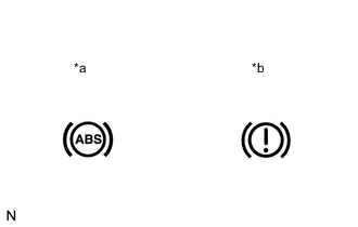
Text in Illustration *a ABS Warning Light *b Brake Warning Light When the ignition switch is turned ON, check that the ABS warning and brake warning lights come on for approximately 3 seconds.
Tech Tips
-
If the brake actuator assembly (skid control ECU) stores any DTCs, the ABS warning and brake warning lights will come on.
-
If any of the indicators remain on or do not come on, proceed to troubleshooting for the light circuits listed below.
Trouble Area See Procedure ABS warning light circuit (Remains on) ABS warning light circuit (Does not come on) Brake warning light circuit (Remains on) Brake warning light circuit (Does not come on) -
-
-
SENSOR CHECK USING TEST MODE (SIGNAL CHECK) (When Using Intelligent Tester)
Tech Tips
-
If the ignition switch is turned from ON to ACC or off during Test Mode (signal check), DTCs recorded during the sensor check will be cleared.
-
During Test Mode (signal check), the brake actuator assembly (skid control ECU) records all DTCs detected in the sensor check. By performing Test Mode (signal check), the codes are cleared if a normal condition is confirmed. The remaining codes are the codes indicating where an abnormality was found.
-
Procedure to enter Test Mode.
-
Turn the ignition switch off.
-
Check that the steering wheel is in the straight-ahead position.
-
Check that the shift lever is in P.
-
Connect the intelligent tester to the DLC3.
-
Turn the ignition switch to ON.
-
Turn the intelligent tester on.
-
Switch the brake actuator assembly (skid control ECU) to Test Mode using the intelligent tester. Enter the following menus: Chassis / ABS/VSC/TRC / Utility / Signal Check.
-
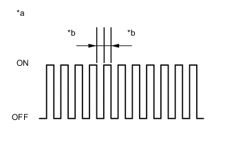
Text in Illustration *a Blinking Pattern in Test Mode *b 0.125 Seconds Check that the ABS warning lights come on for several seconds and then blink in the Test Mode blinking pattern.
Tech Tips
If the ABS warning lights do not blink, inspect the TS and CG terminal circuit and ABS warning light circuits.
Trouble Area See procedure TS and CG terminal circuit ABS warning light circuit (Remains on) ABS warning light circuit (Does not come on)
-
-
-
SPEED SENSOR CHECK (When Using Intelligent Tester)
-
Check the speed sensor signal.
-
Drive the vehicle straight-ahead.
Accelerate the vehicle to a speed of 45 km/h (28 mph) or more for several seconds and check that the ABS warning light goes off.
-
The sensor check may not be completed if wheelspin occurs.
-
The ABS warning light blinks when the sensor check has been completed and the brake pedal is depressed.
-
The ABS warning light comes on immediately after a malfunction has been detected during the speed sensor check.
-
-
-
Stop the vehicle.
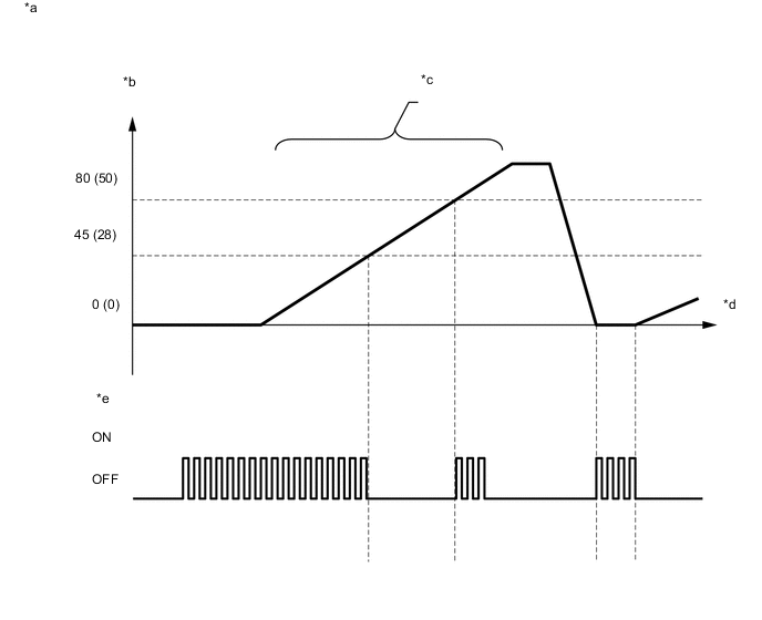
Text in Illustration *a Blinking Pattern in Speed Sensor Check *b Vehicle Speed: km/h (mph) *c Do not spin the wheels *d Time *e ABS Warning Light - - Note
-
The speed sensor check may not be completed if the sensor check is started with the steering wheel turned or one or more wheels spinning.
-
After the ABS warning light goes off and if the vehicle speed exceeds 80 km/h (50 mph), a sensor check code will be stored again. Decelerate or stop the vehicle before the speed reaches 80 km/h (50 mph).
-
If the sensor check has not been completed, the ABS warning light blinks during driving and the ABS system does not operate.
Tech Tips
When the sensor check has been completed, the ABS warning light remains off during driving and blinks in the Test Mode pattern while the vehicle is stationary.
-
-
-
END OF SENSOR CHECK (When Using Intelligent Tester)
-
Text in Illustration *a Blinking Pattern in Test Mode *b 0.125 Seconds If the sensor check is completed, the ABS warning light blinks (Test Mode) when the vehicle stops and the ABS warning light is off while the vehicle is being driven.
Note
If the sensor check is not completed, the ABS warning light blinks even while the vehicle is being driven and the ABS does not operate.
-
-
READ DTC OF SIGNAL CHECK FUNCTION (When Using Intelligent Tester)
-
Read the DTC(s) by following the tester screen.
Note
-
If only the DTCs are displayed, repair the malfunction area and clear the DTCs.
-
If Test Mode sensor check DTCs and other DTCs are displayed or if only Test Mode sensor check DTCs are displayed, repair the malfunctions, clear the DTCs, and perform the Test Mode inspection again.
-
-
List of DTCs.
ABS Sensor DTC Code Detection Item Trouble Area C1271 Low output signal from front speed sensor RH
-
Front speed sensor RH
-
Sensor installation
-
Speed sensor rotor
C1272 Low output signal from front speed sensor LH
-
Front speed sensor LH
-
Sensor installation
-
Speed sensor rotor
C1273 Low output signal from rear speed sensor RH
-
Rear speed sensor RH
-
Sensor installation
-
Speed sensor rotor
C1274 Low output signal from rear speed sensor LH
-
Rear speed sensor LH
-
Sensor installation
-
Speed sensor rotor
C1275 Abnormal change in output signal from front speed sensor RH Speed sensor rotor C1276 Abnormal change in output signal from front speed sensor LH Speed sensor rotor C1277 Abnormal change in output signal from rear speed sensor RH Speed sensor rotor C1278 Abnormal change in output signal from rear speed sensor LH Speed sensor rotor C1279 Acceleration sensor output voltage malfunction
-
Deceleration sensor
-
Sensor installation
Tech Tips
The codes in this table are output only in Test Mode (signal check).
-
-
Turn the ignition switch off and disconnect the intelligent tester.
-
-
SENSOR CHECK USING TEST MODE (SIGNAL CHECK) (When not Using Intelligent Tester)
Tech Tips
-
If the ignition switch is turned from ON to ACC or off during Test Mode (signal check), DTCs recorded during the sensor check will be cleared.
-
During Test Mode (signal check), the brake actuator assembly (skid control ECU) records all DTCs detected in the sensor check. By performing Test Mode (signal check), the codes are cleared if a normal condition is confirmed. The remaining codes are the codes indicating where an abnormality was found.
-
Procedure to enter Test Mode.
-
Turn the ignition switch off.
-
Check that the steering wheel is in the straight-ahead position.
-
Check that the shift lever is in P.
-
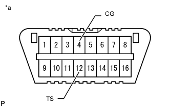
Text in Illustration *a Front view of DLC3 Using SST, connect terminals 12 (TS) and 4 (CG) of the DLC3.
- SST
- 09843-18040
-
Turn the ignition switch to ON.
-
Text in Illustration *a Blinking Pattern in Test Mode *b 0.125 Seconds Check that the ABS warning lights come on for several seconds and then blink in Test Mode.
Tech Tips
If the ABS warning lights do not blink, inspect the TS and CG terminal circuit and ABS warning light circuits.
Trouble Area See procedure TS and CG terminal circuit ABS warning light circuit (Remains on) ABS warning light circuit (Does not come on)
-
-
-
SPEED SENSOR CHECK (When not Using Intelligent Tester)
-
Check the speed sensor signal.
-
Drive the vehicle straight-ahead.
Accelerate the vehicle to a speed of 45 km/h (28 mph) or more for several seconds and check that the ABS warning light goes off.
-
The sensor check may not be completed if wheelspin occurs.
-
The ABS warning light blinks when the sensor check has been completed and the brake pedal is depressed.
-
The ABS warning light comes on immediately after a malfunction has been detected during the speed sensor check.
-
-
-
Stop the vehicle.
Text in Illustration *a Blinking Pattern in Speed Sensor Check *b Vehicle Speed: km/h (mph) *c Do not spin the wheels *d Time *e ABS Warning Light - - Note
-
The speed sensor check may not be completed if the sensor check is started with the steering wheel turned or one or more wheels spinning.
-
After the ABS warning light goes off and if the vehicle speed exceeds 80 km/h (50 mph), a sensor check code will be stored again. Decelerate or stop the vehicle before the speed reaches 80 km/h (50 mph).
-
If the sensor check has not been completed, the ABS warning light blinks during driving and the ABS system does not operate.
Tech Tips
When the sensor check has been completed, the ABS warning light remains on during driving and blinks in the Test Mode pattern while the vehicle is stationary.
-
-
-
END OF SENSOR CHECK (When not Using Intelligent Tester)
-
Text in Illustration *a Blinking Pattern in Test Mode *b 0.125 Seconds If the sensor check is completed, the ABS warning light blinks (Test Mode) when the vehicle stops and the ABS warning light is off while the vehicle is being driven.
Note
If the sensor check is not completed, the ABS warning light will blink even while the vehicle is driven and the ABS will not operate.
-
-
READ DTC OF SIGNAL CHECK FUNCTION (When not Using Intelligent Tester)
-
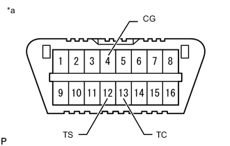
Text in Illustration *a Front view of DLC3 Using SST, connect terminals 12 (TS), 13 (TC) and 4 (CG) of the DLC3.
- SST
- 09843-18040
-
Count the number of blinks of the ABS warning light.
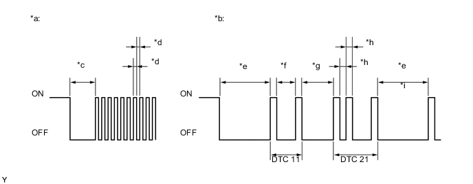
Text in Illustration *a Blinking Pattern in Normal System Code *b Blinking Pattern in Trouble Code (Example Codes 11 and 21) *c 2 Seconds *d 0.25 Seconds *e 4 Seconds *f 1.5 Seconds *g 2.5 Seconds *h 0.5 Seconds *i Repeat - - Note
-
If only DTCs other than Test Mode sensor check DTCs are displayed, repair the malfunctions and clear the DTCs.
-
If Test Mode sensor check DTCs and other DTCs are displayed or if only Test Mode sensor check DTCs are displayed, repair the malfunctions, clear the DTCs, and perform the Test Mode inspection again.
Tech Tips
-
If more than 1 malfunction is detected at the same time, the lowest numbered code will be displayed first.
-
See the list of DTCs (See procedure "A").
-
-
After performing the check, disconnect SST from terminals TS and CG, and TC and CG of the DLC3 and turn the ignition switch off.
-
Turn the ignition switch to ON.
Tech Tips
-
If the ignition switch is not turned to ON after SST is removed from the DLC3, the previous Test Mode will continue.
-
If the ignition switch is turned to ON with terminals TS and CG shorted, the previous Test Mode will continue.
-
-
-
DTC OF TEST MODE (SIGNAL CHECK) FUNCTION (Procedure "A")
ABS Sensor DTC Code Detection Item Trouble Area 71 Low output signal from front speed sensor RH
-
Front speed sensor RH
-
Sensor installation
-
Speed sensor rotor
72 Low output signal from front speed sensor LH
-
Front speed sensor LH
-
Sensor installation
-
Speed sensor rotor
73 Low output signal from rear speed sensor RH
-
Rear speed sensor RH
-
Sensor installation
-
Speed sensor rotor
74 Low output signal from rear speed sensor LH
-
Rear speed sensor LH
-
Sensor installation
-
Speed sensor rotor
75 Abnormal change in output signal from front speed sensor RH Speed sensor rotor 76 Abnormal change in output signal from front speed sensor LH Speed sensor rotor 77 Abnormal change in output signal from rear speed sensor RH Speed sensor rotor 78 Abnormal change in output signal from rear speed sensor LH Speed sensor rotor 79 Acceleration sensor output voltage malfunction
-
Deceleration sensor
-
Sensor installation
Tech Tips
The codes in this table are output only in Test Mode (signal check).
-