FRONT AXLE HUB INSTALLATION

PROCEDURE
-
INSTALL FRONT AXLE HUB BEARING
-
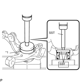
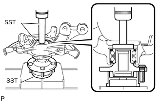
Text in Illustration *1 Axle Hub Bearing Using SST and a press, insert a new axle hub bearing, with its magnetic rotor side facing the inside of the vehicle, until it reaches the end of the steering knuckle.
- SST
- 09950-70010 ( 09951-07100 )
- 09950-60010 ( 09951-00390, 09952-06010 )
- 09950-60020 ( 09951-00730 )
Note
-
Do not remove the inner race because the hub bearing is built into the oil seal.
-
Do not use bearings that have been removed.
-
Do not wipe off any grease that has been applied to new bearings.
-
Do not bring magnets close to the magnetic rotor surface of the bearing.
-
Keep the magnetic rotor surface of the bearing free of foreign matter.
-
-
INSTALL FRONT DISC BRAKE DUST COVER
-
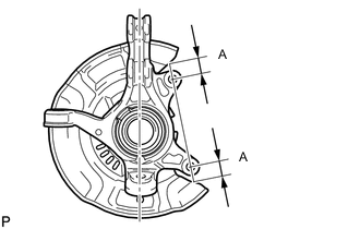
Provisionally install a new disc brake dust cover, as shown in the illustration.
Standard distance A 25.3 mm (0.996 in.) -
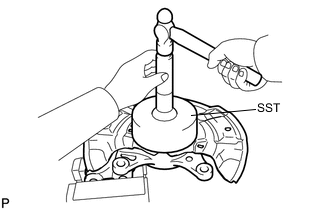
Using SST and a hammer, install the disc brake dust cover.
- SST
- 09223-56010
Note
-
Uniformly press in the disc brake dust cover while sliding SST slightly.
-
Press in the disc brake dust cover until it is securely seated to the pressing-in base.
-
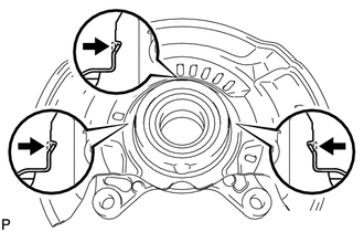
Using a chisel, fix the 3 points on the circumference.
Note
Securely fold each end into the engagement grooves.
-
-
INSTALL FRONT AXLE HUB SUB-ASSEMBLY
-
Using SST and a press, press the axle hub into the steering knuckle.
- SST
- 09950-70010 ( 09951-07100 )
- 09950-60010 ( 09951-00580 )
- 09223-15020
-
-
INSTALL FRONT AXLE HUB HOLE SNAP RING
-
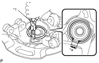
Text in Illustration *1 Snap Ring Pliers *a Speed Sensor Installation Gap Using snap ring pliers, install a new axle hub hole snap ring, as shown in the illustration.
Note
-
Do not overlap the end of the snap ring and the installation hole in the speed sensor on the knuckle side.
-
Do not damage the magnetic rotor surface of the bearing when installing the snap ring.
-
-
-
INSTALL FRONT AXLE ASSEMBLY
-
Align the drive shaft splines and install the axle assembly.
Note
-
Do not damage the lower ball joint.
-
Do not damage the threads of the drive shaft.
-
Do not damage the speed sensor rotor.
-
Do not damage the drive shaft outboard joint boot.
-
-
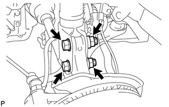
Install the front axle assembly onto the shock absorber with the 2 bolts and 2 nuts.
- Torque:
- 164 N*m { 1672 kgf*cm, 121 ft.*lbf }
Tech Tips
Keep the bolt from rotating while turning the nut.
-
-
INSTALL FRONT LOWER SUSPENSION ARM
-
INSTALL TIE ROD END SUB-ASSEMBLY
-
INSTALL FRONT STABILIZER LINK ASSEMBLY
-
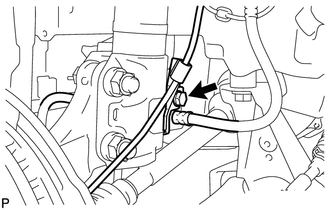
INSTALL FRONT SPEED SENSOR
-
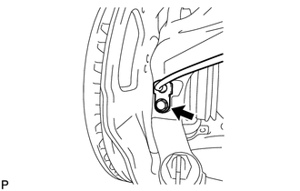
Install the speed sensor onto the steering knuckle with the bolt.
- Torque:
- 8.5 N*m { 87 kgf*cm, 75 in.*lbf }
Note
-
Check that the speed sensor tip and installation portion are free of foreign matter.
-
Install the speed sensor without turning it from its original installation angle.
-
Install the flexible hose and speed sensor with the bolt.
- Torque:
- 29 N*m { 300 kgf*cm, 22 ft.*lbf }
Note
Install the flexible hose and speed sensor without twisting them.
-
-
INSTALL FRONT DISC
-
INSTALL FRONT DISC BRAKE CALIPER ASSEMBLY
-
INSTALL FRONT AXLE SHAFT NUT
-
INSPECT FRONT AXLE HUB BEARING BACKLASH
-
INSPECT FRONT AXLE HUB RUNOUT
-
INSTALL FRONT WHEEL
- Torque:
- 103 N*m { 1050 kgf*cm, 76 ft.*lbf }
-
INSPECT AND ADJUST FRONT WHEEL ALIGNMENT
-
CHECK ABS SENSOR SIGNAL (w/o VSC)
-
CHECK ABS SENSOR SIGNAL (w/ VSC)