FRONT DRIVE SHAFT ASSEMBLY(for 1NZ-FE) REASSEMBLY

PROCEDURE
-
INSTALL FRONT DRIVE SHAFT DUST COVER
-
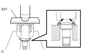
Using SST and a press, install a new dust cover into the inboard joint until it is flush with the end.
- SST
- 09527-10011
Note
-
Install the dust cover in the correct orientation.
-
Do not deform the dust cover.
Tech Tips
Use the same procedure for the RH side as for the LH side.
-
-
INSTALL FRONT DRIVE SHAFT HOLE SNAP RING LH
-
Install a new snap ring.
-
-
INSTALL FRONT DRIVE SHAFT HOLE SNAP RING RH
Tech Tips
Use the same procedure for the RH side as for the LH side.
-
INSTALL FRONT AXLE OUTBOARD JOINT BOOT
-
Wrap the spline of the outboard joint shaft with protective tape.
-
Install new parts onto the outboard joint shaft in the following order.
Installation Order Order Part Name 1. Front No. 2 axle outboard joint boot clamp 2. Front axle outboard joint boot 3. Front axle outboard joint boot clamp -
Pack the joint portion of the outboard joint shaft and the outboard joint boot with grease.
Standard Quantity 116 to 126g (4.1 to 4.4 oz.) -
Install the outboard joint boot onto the outboard joint shaft groove.
Note
Keep the groove free of grease.
Tech Tips
Use the same procedure for the RH side as for the LH side.
-
-
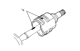
INSTALL FRONT NO. 2 AXLE OUTBOARD JOINT BOOT CLAMP
CAUTION:
Wear protective gloves to avoid injuries to your hands.
-
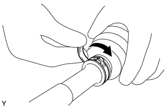
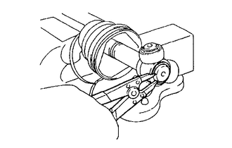
Install a new boot clamp onto the outboard joint boot and provisionally fold back the lever.
Note
-
Set the lever into the guide groove correctly and install the clamp as far into the inner side of the vehicle as possible.
-
Check the band and the lever for any deformation before folding back the lever.
-
-
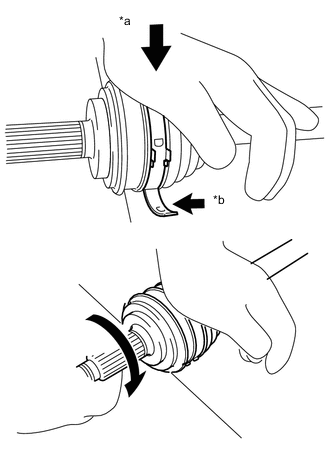
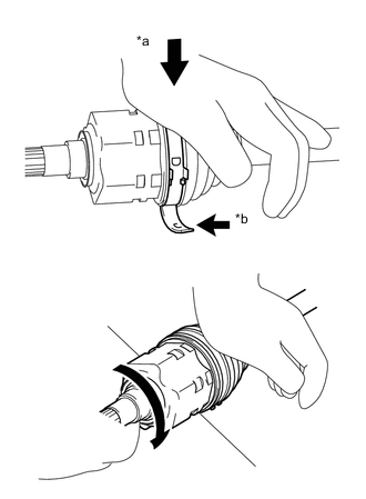
Text in Illustration *a Weight *b Contact Lean your weight on your hand and roll the outboard joint forward while pressing the outboard joint against the work plane. Roll the outboard joint and fold the lever until a click sound can be heard.
Note
-
Do not damage the deflector.
-
Make sure that the outboard joint is in direct contact with the work plane.
-
-
Using a plastic hammer, tap the buckle to fix it while adjusting the clearance between the lever and the groove to make the clearances between the buckle edge and the lever end even.
Note
Do not damage the outboard joint boot.
Tech Tips
Use the same procedure for the RH side as for the LH side.
-
-
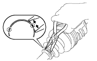
INSTALL FRONT AXLE OUTBOARD JOINT BOOT CLAMP
CAUTION:
Wear protective gloves to avoid injuries to your hands.
-
Install a new boot clamp onto the outboard joint boot and provisionally fold back the lever.
Note
-
Set the lever into the guide groove correctly.
-
Check the band and the lever for any deformation before folding back the lever.
-
-
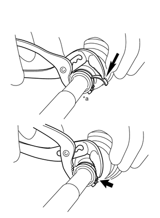
Text in Illustration *a Place the tip near the center of the lever. Using water pump pliers, pinch the boot clamp to provisionally fix it.
-
Using a plastic hammer, tap the buckle to fix it while adjusting the clearance between the lever and the groove to make the clearances between the buckle edge and the lever end even.
Note
Do not damage the outboard joint boot.
Tech Tips
Use the same procedure for the RH side as for the LH side.
-
-
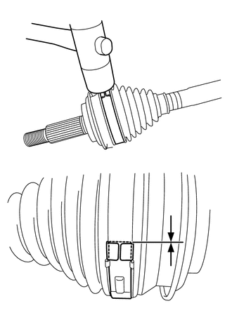
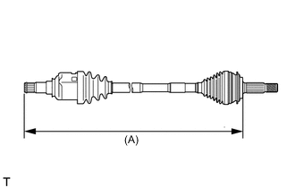
INSTALL FRONT DRIVE SHAFT DAMPER LH
-
Install the drive shaft damper onto dimension (A) shown in the illustration.
Dimension (A) Standard Length 204.5 to 208.5 mm (8.05 to 8.21 in.) Note
Install the damper in the correct orientation.
-
-
INSTALL FRONT DRIVE SHAFT DAMPER RH
-
Text in Illustration *a Front No. 2 drive shaft damper RH *b Front No. 1 drive shaft damper RH Install the drive shaft damper onto dimension (A) shown in the illustration.
Dimension (A) Front No. 1 drive shaft damper RH Front No. 2 drive shaft damper RH 425.6 to 429.6 mm
(16.76 to 16.91 in.)
161 to 165 mm
(6.34 to 6.50 in.)
Note
Install the damper in the correct orientation.
-
-
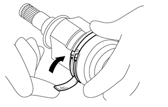
INSTALL FRONT DRIVE SHAFT DAMPER CLAMP LH
Text in Illustration *a One Touch Type *b Claw Engagement Type
-
One touch type:
-
Install a new damper clamp onto the front drive shaft damper and fix the damper clamp with a screwdriver.
-
-
Claw engagement type:
-
Using needle-nose pliers, install a new damper clamp as shown in the illustration.
-
-
-
INSTALL FRONT DRIVE SHAFT DAMPER CLAMP RH
Tech Tips
Use the same procedure for the RH side as for the LH side.
-
INSTALL FRONT DRIVE INBOARD JOINT ASSEMBLY
-
Install a new parts onto the outboard joint shaft in the following order.
Installation Order Order Part Name 1. Front axle inboard joint boot clamp 2. Front axle inboard joint boot 3. Front No. 2 axle inboard joint boot clamp -
Fix the outboard joint shaft in a vise between aluminum plates.
Note
Do not overtighten the vise.
-
Remove the protective tape.
-
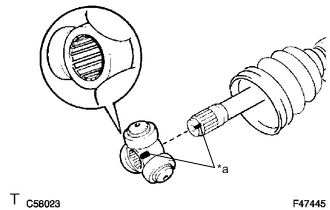
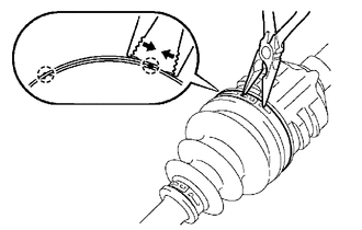
Text in Illustration *a Matchmark Align the matchmarks and install the tripod joint onto the outboard joint shaft.
Note
Face the serrated side of the tripod joint outward and install it onto the outboard joint end.
-
Using a brass bar and hammer, install the tripod joint.
Note
-
Do not hit the rollers.
-
Keep the tripod joint free of foreign matter.
-
-
Using a snap ring expander, install a new snap ring.
-
Pack the inboard joint with grease.
Standard Quantity 125 to 135g (4.4 to 4.8 oz.) -
Text in Illustration *a Matchmark Align the matchmarks and install the inboard joint onto the outboard joint shaft.
Tech Tips
Use the same procedure for the RH side as for the LH side.
-
-
INSTALL FRONT AXLE INBOARD JOINT BOOT
-
Install the inboard joint boot into the grooves of the inboard joint and outboard joint shaft.
Note
Keep the grooves free of grease.
Tech Tips
Use the same procedure for the RH side as for the LH side.
-
-
INSTALL FRONT AXLE INBOARD JOINT BOOT CLAMP
CAUTION:
Wear protective gloves to avoid injuries to your hands.
-
One touch type:
-
Install a new boot clamp onto the inboard joint boot and provisionally fold back the lever.
Note
-
Set the lever into the guide groove correctly.
-
Check the band and the lever for any deformation before folding back the lever.
-
-

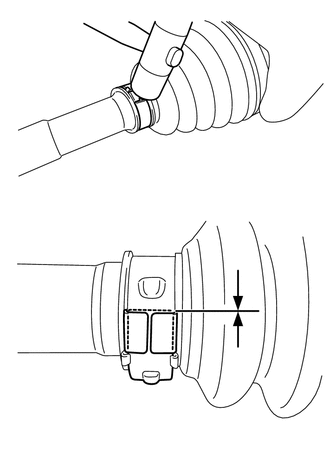
Text in Illustration *a Place the tip near the center of the lever. Using water pump pliers, pinch the boot clamp to provisionally fix it.
-
Using a plastic hammer, tap the buckle to fix it while adjusting the clearance between the lever and the groove to make the clearances between the buckle edge and the lever end even.
Note
Do not damage the inboard joint boot.
-
-
Claw engagement type:
-
Using needle-nose pliers, install a new clamp as shown in the illustration.
Note
-
Do not damage the boot.
-
Do not deform the claw of the hook.
Tech Tips
Use the same procedure for the RH side as for the LH side.
-
-
-
-
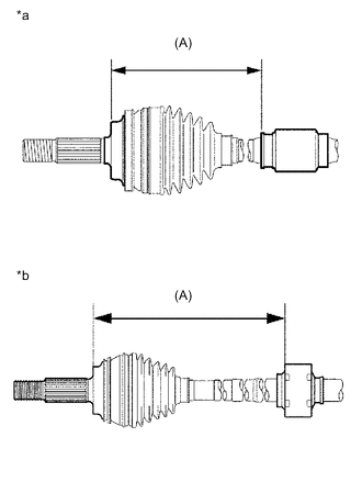
INSTALL FRONT NO. 2 AXLE INBOARD JOINT BOOT CLAMP
-
Install a new boot clamp onto the inboard joint boot.
-
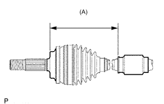
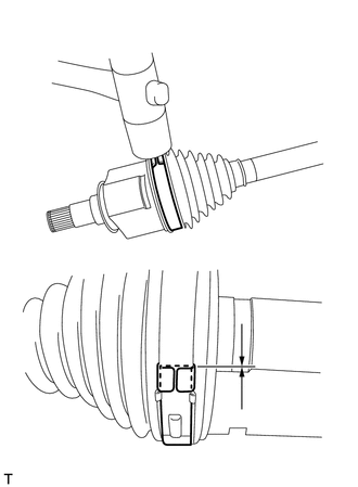
Adjust dimension (A) until the drive shaft is within the specified length.
Dimension (A) LH RH 584.3 mm (23.00 in.) 826.3 mm (32.53 in.) -
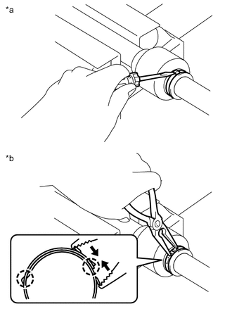
One touch type:
-
Install a new boot clamp onto the inboard joint boot and provisionally fold back the lever.
CAUTION:
Wear protective gloves to avoid injuries to your hands.
Note
-
Set the lever into the guide groove correctly.
-
Check the band and the lever for any deformation before folding back the lever.
-
-
Text in Illustration *a Weight *b Contact Lean your weight on your hand and roll the outboard joint forward while pressing the outboard joint against the work plane. Roll the outboard joint and fold the lever until a click sound can be heard.
Note
-
Do not damage the deflector.
-
Make sure that the inboard joint is in direct contact with the work plane.
-
-
Using a plastic hammer, tap the buckle to fix it while adjusting the clearance between the lever and the groove to make the clearances between the buckle edge and the lever end even.
Note
Do not damage the boot.
-
-
Claw engagement type:
-
Using needle-nose pliers, engage the 2 claws and install the boot clamp as shown in the illustration.
Note
-
Do not damage the boot.
-
Do not deform the claw of the hook.
Tech Tips
Use the same procedure for the RH side as for the LH side.
-
-
-
-
INSPECT FRONT DRIVE SHAFT ASSEMBLY