FRONT DRIVE SHAFT ASSEMBLY(for 1ND-TV) INSTALLATION

PROCEDURE
-
INSTALL FRONT DRIVE SHAFT ASSEMBLY LH
-
Coat the spline of the inboard joint with gear oil.
-
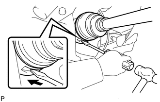
Align the inboard joint splines and install the drive shaft with a screwdriver and hammer.
Note
-
Face the cut area of the front drive shaft hole snap ring downward.
-
Do not damage the oil seal.
-
Do not damage the inboard joint boot.
Tech Tips
Confirm whether the drive shaft is securely driven in by checking the reaction force and sound.
-
-
-
INSTALL FRONT DRIVE SHAFT ASSEMBLY RH
Tech Tips
Use the same procedure for the RH side as for the LH side.
-
INSTALL FRONT AXLE ASSEMBLY LH
-
INSTALL FRONT AXLE ASSEMBLY RH
Tech Tips
Use the same procedure for the RH side as for the LH side.
-
INSTALL FRONT LOWER SUSPENSION ARM SUB-ASSEMBLY LH
-
INSTALL FRONT LOWER SUSPENSION ARM SUB-ASSEMBLY RH
Tech Tips
Use the same procedure for the RH side as for the LH side.
-
INSTALL TIE ROD END SUB-ASSEMBLY LH
-
INSTALL TIE ROD END SUB-ASSEMBLY RH
Tech Tips
Use the same procedure for the RH side as for the LH side.
-
INSTALL FRONT STABILIZER LINK ASSEMBLY LH
-
INSTALL FRONT STABILIZER LINK ASSEMBLY RH
Tech Tips
Use the same procedure for the RH side as for the LH side.
-
INSTALL FRONT SPEED SENSOR LH
-
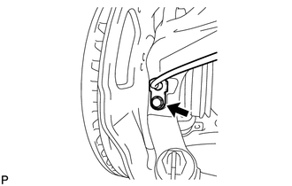
Install the front speed sensor onto the steering knuckle with the bolt.
- Torque:
- 8.5 N*m { 87 kgf*cm, 75 in.*lbf }
Note
-
Check that the speed sensor tip and installation portion are free of foreign matter.
-
Install the speed sensor without turning it from its original installation angle.
-
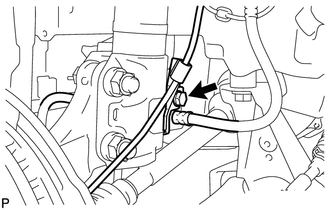
Install the flexible hose and front speed sensor with the bolt.
- Torque:
- 29 N*m { 300 kgf*cm, 22 ft.*lbf }
Note
Install the flexible hose and speed sensor without twisting them.
-
-
INSTALL FRONT SPEED SENSOR RH
Tech Tips
Use the same procedure for the RH side as for the LH side.
-
INSTALL FRONT AXLE SHAFT NUT LH
-
Clean the threaded parts on the front drive shaft and axle shaft nut using a non-residue solvent.
Note
-
Be sure to perform this work for a new front drive shaft.
-
Keep the threaded parts free of oil and foreign objects.
-
-
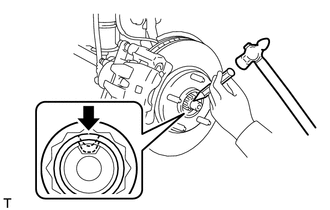
Using a 30 mm socket wrench, install a new front axle shaft nut.
- Torque:
- 216 N*m { 2203 kgf*cm, 159 ft.*lbf }
-
Using a chisel and hammer, stake the axle shaft nut.
-
-
INSTALL FRONT AXLE SHAFT NUT RH
Tech Tips
Use the same procedure for the RH side as for the LH side.
-
ADD MANUAL TRANSAXLE OIL (for Manual Transaxle)
-
ADD MANUAL TRANSAXLE OIL (for Multi-Mode Manual Transaxle)
See page MULTI-MODE MANUAL TRANSAXLE (EC65A) > MULTI-MODE MANUAL TRANSAXLE OIL > REPLACEMENT > ADD MANUAL TRANSAXLE OIL
-
INSPECT MANUAL TRANSAXLE OIL (for Manual Transaxle)
-
INSPECT MANUAL TRANSAXLE OIL (for Multi-Mode Manual Transaxle)
See page MULTI-MODE MANUAL TRANSAXLE (EC65A) > MULTI-MODE MANUAL TRANSAXLE OIL > ON-VEHICLE INSPECTION > INSPECT MANUAL TRANSAXLE OIL
-
INSPECT FOR TRANSAXLE OIL LEAK
-
INSTALL ENGINE UNDER COVER RH
-
INSTALL ENGINE UNDER COVER LH
-
INSTALL CENTER ENGINE UNDER COVER
-
INSTALL FRONT WHEEL
- Torque:
- 103 N*m { 1050 kgf*cm, 76 ft.*lbf }
-
INSPECT AND ADJUST FRONT WHEEL ALIGNMENT