FRONT SUSPENSION MEMBER REMOVAL

PROCEDURE
-
POSITION FRONT WHEELS FACING STRAIGHT AHEAD
-
FIX STEERING WHEEL
-
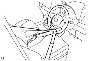
Use a seat belt to fix the steering wheel assembly, in order to avoid breakage of the spiral cable.
-
-
REMOVE COLUMN HOLE COVER SILENCER SHEET
-
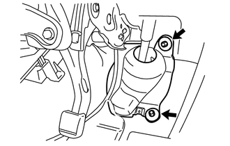
Fold back the floor carpet, and then remove the 2 clips and column hole cover silencer sheet.
-
-
SEPARATE STEERING SLIDING YOKE SUB-ASSEMBLY
-
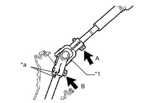
Text in Illustration *1 Steering Sliding Yoke Sub-assembly *a Matchmark Place matchmarks on the steering sliding yoke sub-assembly and the steering gear assembly.
-
Loosen bolt A, remove bolt B and separate the steering sliding yoke sub-assembly from the steering gear assembly.
-
-
SEPARATE NO. 1 STEERING COLUMN HOLE COVER SUB-ASSEMBLY
-
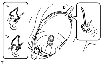
Text in Illustration *a Type A *b Type B Remove clip A, separate clip B from the body and separate the No. 1 steering column hole cover sub-assembly.
Note
Do not damage clip B.
Tech Tips
For clip A, there are 2 types: Type A and Type B.
-
-
REMOVE FRONT WHEEL
-
SEPARATE FRONT STABILIZER LINK ASSEMBLY LH
-
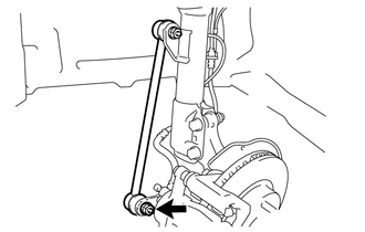
Remove the nut and separate the stabilizer link from the steering knuckle.
Tech Tips
If the ball joint turns together with the nut, use a socket hexagon wrench 6 to hold the stud.
-
-
SEPARATE FRONT STABILIZER LINK ASSEMBLY RH
Tech Tips
Use the same procedure for the RH side as for the LH side.
-
SEPARATE TIE ROD END SUB-ASSEMBLY LH
-
Remove the cotter pin and castle nut.
-
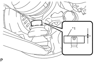
Text in Illustration *1 Spacer B Install SST (spacer B) to the threaded section of the tie rod end.
- SST
- 09960-20010 ( 09961-02060 )
Note
Make sure the upper ends of the threaded section of the tie rod end and SST (spacer B) are aligned.
-
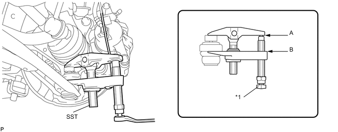
Using SST, separate the tie rod end from the front axle assembly.
Text in Illustration *1 Place the wrench here - - - SST
- 09960-20010 ( 09961-02010 )
Note
-
Make sure to tie the string of SST to the vehicle to prevent SST from dropping.
-
Install SST so that A and B are parallel.
-
Be sure to place the wrench on the part indicated in the illustration.
-
Do not damage the ball joint dust cover.
-
Do not damage the front disc brake dust cover.
-
-
SEPARATE TIE ROD END SUB-ASSEMBLY RH
Tech Tips
Use the same procedure for the RH side as for the LH side.
-
SEPARATE FRONT LOWER SUSPENSION ARM SUB-ASSEMBLY LH
-
Remove the clip and castle nut.
-
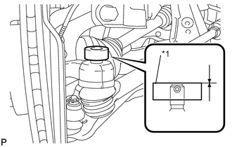
Text in Illustration *1 Spacer B Install SST (spacer B) to the threaded section of the lower ball joint.
- SST
- 09960-20010 ( 09961-02060 )
Note
Make sure the upper ends of the threaded section of the lower ball joint and SST (spacer B) are aligned.
-
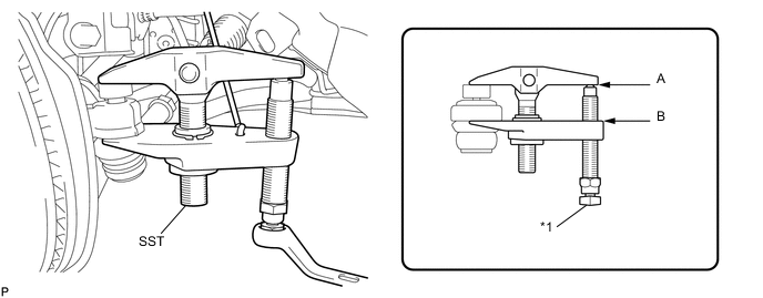
Using SST, separate the lower arm.
Text in Illustration *1 Place the wrench here - - - SST
- 09960-20010 ( 09961-02010 )
Note
-
Make sure to tie the string of SST to the vehicle to prevent SST from dropping.
-
Install SST so that A and B are parallel.
-
Be sure to place the wrench on the part indicated in the illustration.
-
Do not damage the lower ball joint dust cover.
-
Do not damage the drive shaft outboard joint boots.
-
Do not damage the front disc brake dust cover.
-
-
SEPARATE FRONT LOWER SUSPENSION ARM SUB-ASSEMBLY RH
Tech Tips
Use the same procedure for the RH side as for the LH side.
-
SUPPORT ENGINE ASSEMBLY
-
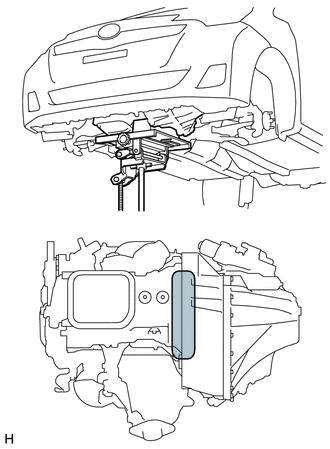
Using a transmission jack and wooden block, support the engine assembly with transaxle.
Text in Illustration 
Attachment Placement Position
-
-
REMOVE FRONT SUSPENSION CROSSMEMBER SUB-ASSEMBLY
-
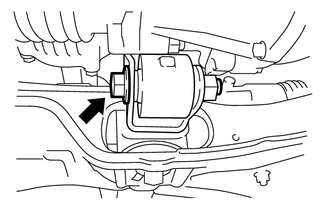
Remove the bolt and separate the engine moving control rod.
-
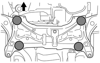
Place wooden blocks or plate lift attachments in the positions shown in the illustration and set an engine lifter underneath the front suspension crossmember.
Text in Illustration 
Front of the Vehicle Attachment Placement Positions Note
-
Place the wooden blocks or plate lift attachments so that the front suspension crossmember sub-assembly is level.
-
As the front suspension crossmember subassembly is very heavy, be sure to support it securely.
-
-
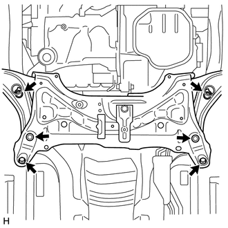
Remove the 6 bolts and front suspension crossmember sub-assembly.
-
-
REMOVE POWER STEERING GEAR
-
REMOVE FRONT STABILIZER BRACKET LH
-
REMOVE FRONT STABILIZER BRACKET RH
Tech Tips
Use the same procedure for the RH side as for the LH side.
-
REMOVE FRONT STABILIZER BAR
-
REMOVE FRONT LOWER SUSPENSION ARM SUB-ASSEMBLY LH
-
REMOVE FRONT LOWER SUSPENSION ARM SUB-ASSEMBLY RH
Tech Tips
Use the same procedure for the RH side as for the LH side.
-
REMOVE ENGINE MOVING CONTROL ROD COVER (for Cold Area)
-
Remove the 2 clips and the engine mounting control rod cover.
-
-
REMOVE ENGINE MOVING CONTROL ROD
-
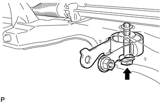
Remove the bolt and the engine moving control rod.
-