CONTINUOUSLY VARIABLE TRANSAXLE SYSTEM Transmission Control Switch Circuit
DESCRIPTION
After moving the shift lever to M, it is possible to switch the shift range between "1" (M1 range) and "7" (M7 range) using the transmission control switch.
Moving the shift lever to "+" once raises the shift range by one, and moving the shift lever to "-" lowers the shift range by one.
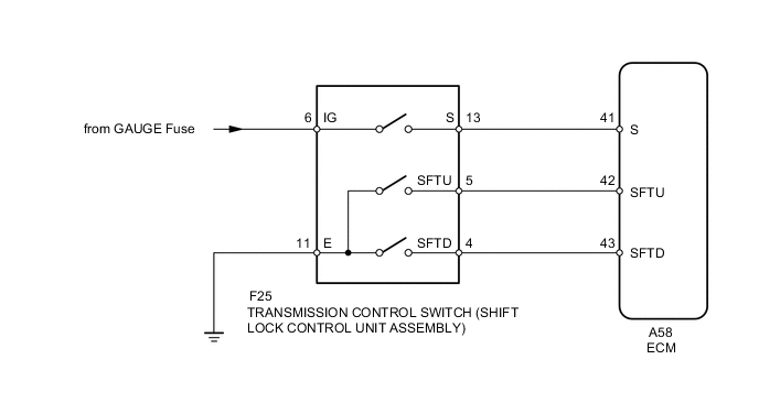
WIRING DIAGRAM
PROCEDURE
-
INSPECT TRANSMISSION CONTROL SWITCH (SHIFT LOCK CONTROL UNIT ASSEMBLY)
-
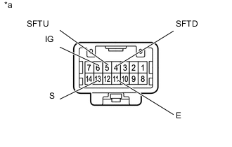
Text in Illustration *a Component without harness connected
(Transmission Control Switch (Shift lock control unit assembly))
Disconnect the F25 transmission control switch connector.
-
Measure the resistance according to the value(s) in the table below.
Standard Resistance Tester Connection Condition Specified Condition 6 (IG) - 13 (S) Shift lever in M, "+" or "-" Below 1 Ω 5 (SFTU) - 11 (E) Shift lever held in "+" (Up-shift) Below 1 Ω 4 (SFTD) - 11 (E) Shift lever held in "-" (Down-shift) Below 1 Ω 6 (IG) - 13 (S) Shift lever not in M, "+" or "-" 10 kΩ or higher 5 (SFTU) - 11 (E) Shift lever in M 10 kΩ or higher 4 (SFTD) - 11 (E) Shift lever in M 10 kΩ or higher
NG 
REPLACE TRANSMISSION CONTROL SWITCH (SHIFT LOCK CONTROL UNIT ASSEMBLY) Click here
OK 
-
-
CHECK HARNESS AND CONNECTOR (TRANSMISSION CONTROL SWITCH - BATTERY AND BODY GROUND)
-
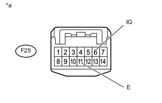
Text in Illustration *a Front view of wire harness connector
(to Transmission Control Switch (Shift lock control unit assembly))
Disconnect the F25 transmission control switch connector.
-
Measure the voltage according to the value(s) in the table below.
Standard Voltage Tester Connection Switch Condition Specified Condition F25-6 (IG) - Body ground Ignition switch ON 11 to 14 V F25-6 (IG) - Body ground Ignition switch off Below 1 V -
Turn the ignition switch off.
-
Measure the resistance according to the value(s) in the table below.
Standard Resistance Tester Connection Condition Specified Condition F25-11 (E) - Body ground Always Below 1 Ω
NG
REPAIR OR REPLACE HARNESS OR CONNECTOR
OK
-
-
CHECK HARNESS AND CONNECTOR (TRANSMISSION CONTROL SWITCH - ECM)
-
Disconnect the A58 ECM connectors.
-
Turn the ignition switch to ON.
-
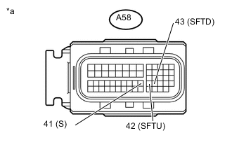
Text in Illustration *a Front view of wire harness connector
(to ECM)
Measure the voltage according to the value(s) in the table below.
Standard Voltage Tester Connection Condition Specified Condition A58-41 (S) - Body ground
-
Ignition switch ON
-
Shift lever in M, "+" or "-"
11 to 14 V A58-41 (S) - Body ground
-
Ignition switch ON
-
Shift lever not in M, "+" or "-"
Below 1 V -
-
Turn the ignition switch off.
-
Measure the resistance according to the value(s) in the table below.
Standard Resistance Tester Connection Condition Specified Condition A58-42 (SFTU) - Body ground Shift lever held in "+" (Up-shift) Below 1 Ω A58-43 (SFTD) - Body ground Shift lever held in "-" (Down-shift) Below 1 Ω A58-42 (SFTU) - Body ground Shift lever in M 10 kΩ or higher A58-43 (SFTD) - Body ground Shift lever in M 10 kΩ or higher
NG
REPAIR OR REPLACE HARNESS OR CONNECTOR
OK
-
-
REPLACE ECM
-
Replace the ECM Click here.
NEXT
-
-
PERFORM INITIALIZATION
Note
-
Performing reset memory will clear the learned values of both the yaw rate sensor (deceleration sensor 0 point calibration) and CVT oil pressure (CVT oil pressure calibration). Make sure to perform reset memory, yaw rate sensor 0 point calibration and CVT oil pressure calibration when replacing any of the parts shown in the following table:
Replaced Part
-
Continuously variable transaxle assembly
-
ECM
-
Skid control computer (w/o VSC)
-
Oil pressure sensor
-
Deceleration sensor (w/o VSC)
-
Airbag sensor assembly (Yaw rate sensor) (w/ VSC)
-
-
After performing reset memory, always perform yaw rate sensor (deceleration sensor 0 point) calibration first, and then CVT oil pressure calibration.
-
Always perform 0 point calibration with the vehicle on level ground.
-
Do not shake or vibrate the vehicle during 0 point calibration.
-
Using the intelligent tester, perform reset memory, deceleration sensor 0 point calibration and CVT oil pressure calibration Click here.
-
Check that no DTC is stored.
NEXT
END
-