CONTINUOUSLY VARIABLE TRANSAXLE SYSTEM, Diagnostic DTC:P1585
| DTC Code | DTC Name |
|---|---|
| P1585 | Acceleration Sensor Circuit |
DESCRIPTION
The ECM determines the vehicle inclination based on a signal from the deceleration sensor to perform neutral control. If a malfunction is determined in the deceleration sensor based on a malfunction signal from the brake actuator assembly, the ECM cancels neutral control as a fail-safe function.
Tech Tips
-
The signal of the deceleration sensor is sent to the brake actuator assembly via the CAN communication system.
-
If CAN communication DTCs are output, perform troubleshooting for those DTCs first.
| DTC No. | DTC Detection Condition
|
Trouble Area |
|---|---|---|
| P1585 |
|
|
|
||
|
WIRING DIAGRAM
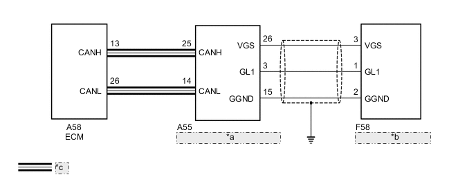
| *a | Brake actuator Assembly (Skid Control ECU) |
| *b | Deceleration Sensor |
| *c | CAN Communication Line |
PROCEDURE
-
CHECK DTC OUTPUT (CAN COMMUNICATION SYSTEM)
-
Check for DTCs of the CAN communication system Click here.
Result Result Proceed to DTCs are not output A DTCs are output B
B 
GO TO CAN COMMUNICATION SYSTEM Click here
A 
-
-
READ VALUE USING GTS (G SENSOR)
-
Connect the GTS to the DLC3.
-
Turn the ignition switch to ON.
-
Turn the GTS on.
-
Enter the following menus: Powertrain / Engine and ECT / Data List.
-
In accordance with the display on the GTS, read the Data List.
Engine and ECT Tester Display Measurement Item/Range Normal Condition Diagnostic Note G sensor Converted output voltage of deceleration sensor/
min.: 0 V
max.: 5 V
Displays converted voltage of deceleration sensor
-
2.31 V to 2.69 V: Vehicle on level ground
-
1.88 V to 2.5 V: Decelerating
-
2.5 V to 3.11 V: Accelerating
-
Set to 1.87 V: G sensor malfunction
-
Set to 1.87 V: Communication malfunction
- Result Result Proceed to Data displayed is not within Normal Condition range A Data displayed is within Normal Condition range B -
B 
REPLACE BRAKE ACTUATOR ASSEMBLY Click here
A
-
-
CHECK HARNESS AND CONNECTOR (BRAKE ACTUATOR ASSEMBLY - DECELERATION SENSOR)
-
Disconnect the brake actuator assembly (skid control ECU) connector.
-
Disconnect the deceleration sensor connector.
-
Measure the resistance according to the value(s) in the table below.
Standard Resistance (Check for Open) Tester Connection Condition Specified Condition A55-3 (GL1) - F58-1 (GL1) Always Below 1 Ω A55-15 (GGND) - F58-2 (GGND) Always Below 1 Ω A55-26 (VGS) - F58-3 (VGS) Always Below 1 Ω Standard Resistance (Check for Short) Tester Connection Condition Specified Condition A55-3 (GL1) or F58-1 (GL1) - Body ground Always 10 kΩ or higher A55-15 (GGND) or F58-2 (GGND) - Body ground Always 10 kΩ or higher A55-26 (VGS) or F58-3 (VGS) - Body ground Always 10 kΩ or higher
NG
REPAIR OR REPLACE HARNESS OR CONNECTOR
OK
-
-
CHECK HARNESS AND CONNECTOR (VGS TERMINAL VOLTAGE)
-
Check that the deceleration sensor is correctly installed and that there is no defect in connector connection.
-
Connect the brake actuator assembly (skid control ECU) connector.
-
Turn the ignition switch to ON.
-
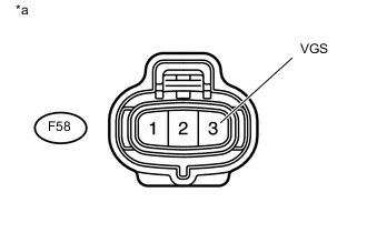
Text in Illustration *a Front view of wire harness connector
(to Deceleration Sensor)
Measure the voltage according to the value(s) in the table below.
Standard Voltage Tester Connection Condition Specified Condition F58-3 (VGS) - F58-2 (GGND) Ignition switch ON 4.5 to 5.5 V
NG
REPAIR OR REPLACE HARNESS OR CONNECTOR
OK
-
-
REPLACE DECELERATION SENSOR
-
Replace the deceleration sensor Click here.
NEXT
-
-
PERFORM INITIALIZATION
Note
-
Performing reset memory/initialization will clear the learned value of the deceleration sensor (deceleration sensor zero point calibration) and the CVT oil pressure (CVT oil pressure calibration). Make sure to perform reset memory, deceleration sensor zero point calibration, and CVT oil pressure calibration when replacing any of the parts shown in the following table:
Replaced Part
-
Continuously variable transaxle assembly
-
ECM
-
Brake actuator assembly (Skid control ECU)
-
Oil pressure sensor
-
Deceleration sensor
-
-
After reset memory, always perform deceleration sensor (deceleration sensor zero point) calibration first, and then the CVT oil pressure calibration.
-
Always perform the zero point calibration with the vehicle on level ground.
-
Do not shake or vibrate the vehicle during the zero point calibration.
-
Using the GTS, perform the reset memory, deceleration sensor zero point calibration and CVT oil pressure calibration Click here.
-
Check for DTCs again Click here.
NEXT
END
-
-
REPLACE BRAKE ACTUATOR ASSEMBLY
-
Replace the brake actuator assembly (skid control ECU) Click here.
NEXT
-
-
PERFORM INITIALIZATION
Note
-
Performing reset memory/initialization will clear the learned value of the deceleration sensor (deceleration sensor zero point calibration) and the CVT oil pressure (CVT oil pressure calibration). Make sure to perform reset memory, deceleration sensor zero point calibration, and CVT oil pressure calibration when replacing any of the parts shown in the following table:
Replaced Part
-
Continuously variable transaxle assembly
-
ECM
-
Brake actuator assembly (Skid control ECU)
-
Oil pressure sensor
-
Deceleration sensor
-
-
After reset memory, always perform deceleration sensor (deceleration sensor zero point) calibration first, and then the CVT oil pressure calibration.
-
Always perform the zero point calibration with the vehicle on level ground.
-
Do not shake or vibrate the vehicle during the zero point calibration.
-
Using the GTS, perform the reset memory, deceleration sensor zero point calibration and CVT oil pressure calibration Click here.
-
Check for DTCs again Click here.
NEXT
END
-